


7-2
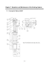
1) Relay box:I
t is an electric component, in which the control board is incorporated.
Please refer to 7.2.
2) Emergency stop button: In AUTO operation, hoisting operation stops when the emergency stop button
is pressed. To resume the hoisting operation, re-press the up/down switches
of the indicator. In MANU operation, if the emergency stop button is pressed
while the manual up/down switch is held down, the hoist operation stops
while the button is pressed. However, please note that the hoisting operation
re-starts as soon as the emergency stop button is released. The hoisting
operation stops if this switch is pressed during hoisting operation. (for more
details, refer to 7.2.)
3)Cable gland:
The connectors which connect the cables of the transducer and the cables of
the transmitter/receiver are contained in this box.
4) Junction box:
The box stores and connects a transducer cable and a cable of a
transmitter and receiver unit.
5) Metal cable fixing:
It fixes the cables of the a transmitter/receiver.
6) Limit switch:
This switch is for the upper and lower limits of the hoisting operation. The
hoisting operation stops when this switch is turned ON.
7) Guide ring:
It reduces the load on the hoist pipe caused by movement resistance or
ibration when the transducer is projected.
8) Dome:
It is what the transducer is built in.
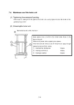
9) Gland follower:
It presses down the gland packing with four bolts(M12) to keep it watertight.
10)
Feed screw:
It converts the rotating force of the hoist motor(13) into a linear motion to
move the hoist pipe up and down.
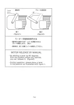
11) Motor shaft cover:
A micro switch is installed inside this cover to disable the electric motor drive
when the cover is removed.
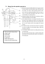
12) Manual handle:
This handle is used for hoisting operation while the power supply is turned
OFF. (For more details, refer to 7.3 Manual handle operation instructions)
13) Hoist motor:
This is the drive motor for the hoisting operation.
(Specification)
f
3-220V , 1.5 kW gear motor with brake
14) Skirt:
A skirt is welded to the bottom of a boat to store the projection part of the
hoist unit.
15) Zinc plate:
Electrolytic corrosion protective zinc plate. This should be replaced
periodically.
16) Lead switch:
It detects the number of rotations and direction of the feed screw using the
magnet attached to the feed screw(10).
Summary of Contents for KCS-3500
Page 1: ...Model KCS 3500 Color Scanning Sonar Operation Manual Ver 1 6...
Page 2: ......
Page 16: ......
Page 26: ......
Page 62: ......
Page 70: ...7 8...
Page 85: ......
Page 86: ......
Page 87: ......
Page 88: ......
Page 89: ......
Page 90: ......
Page 91: ......
Page 92: ......
Page 93: ......
Page 94: ......
Page 95: ......
Page 96: ......
Page 97: ......
Page 98: ......
Page 99: ......
Page 100: ......
Page 101: ......
Page 102: ......


