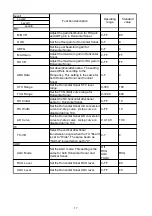


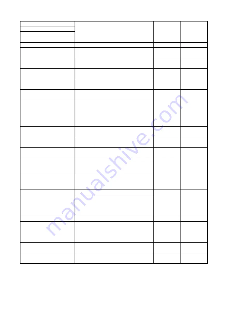
Level1
Level2
Level3
Level4
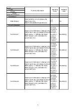
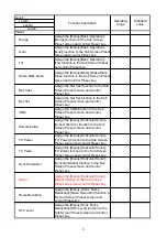
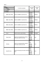
RX
MIN VR
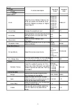
Adjust the gain distribution for RX gain
and ABF gain in Horizontal Sonar.
0-FF
80
GOS
Set the offset gain for Horizontal Sonar. 0-F
8
ABFG
Set the post beamform gain for
Horizontal Sonar.
0-F
0
MAX Gain
Adjust the maximum gain in Horizontal
Sonar.
0-FF
FF
RX VR
Adjust the maximum gain for RX gain in
Horizontal Sonar.
0-FF
FF
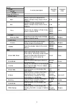
ABS Data
Set absorption/attenuation. The setting
value differs according to the
Frequency. This setting is the same for
both Horizontal Sonar and Vertical
Sonar.
0-F
4
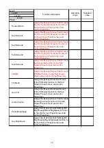
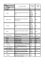
STC Range
Set the Horizontal Sonar STC level
range.
0-300
160
TVG Range
Set the TVG (Mid) curve range for
Horizontal Sonar.
0-1200
640
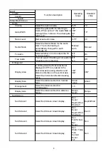
RX Clutter
Adjust the RX horizontal directional
angle for Horizontal Sonar.
0-FF
10
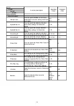
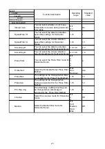
RX Width
Set the Horizontal Sonar AD conversion
curve to 2-step curve. 2-step curve is
disabled during 10.0.
0-FF
10
AD Curve
Set the Horizontal Sonar AD conversion
curve to 2-step curve. 2-step curve is
disabled during 10.0.
0.0-10.0
10.0
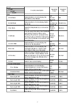
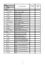
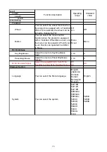
TX
TX-VB
Select the vertical directional
transmission angle when the TX "Beam"
is set to "Wide". The same beam as
"Normal" is used when set to "0".
0-7
4
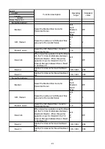
AGC
AGC Mode
Set the AGC mode. This setting is the
same for both Horizontal Sonar and
Vertical Sonar.
Off
RCG
AGC
TAGC
RCG
RCG Level
Set the Horizontal Sonar RCG level.
0-FF
80
AGC Level
Set the Horizontal Sonar AGC level.
0-FF
40
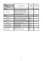
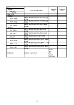
Function description
Operating
range
Standard
value
17
Summary of Contents for KCS-5200
Page 1: ...Model KCS 5200 Color Scanning Sonar Operation Manual Ver 1 48 E Rev 0...
Page 2: ......
Page 14: ......
Page 22: ...2 4...
Page 28: ...3 6...
Page 50: ...5 16...
Page 78: ...6 28 Menu Screen Sub Screen Orthogonal Display Axis...
Page 80: ...6 30...
Page 84: ...7 4...
Page 90: ...8 6...
Page 106: ...9 16...
Page 116: ...10 10...