


6-24
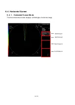
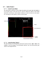
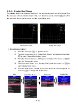
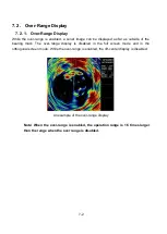
6. 8. Orthogonal Screen
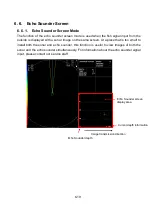
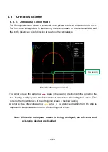
6. 8. 1. Orthogonal Screen Mode
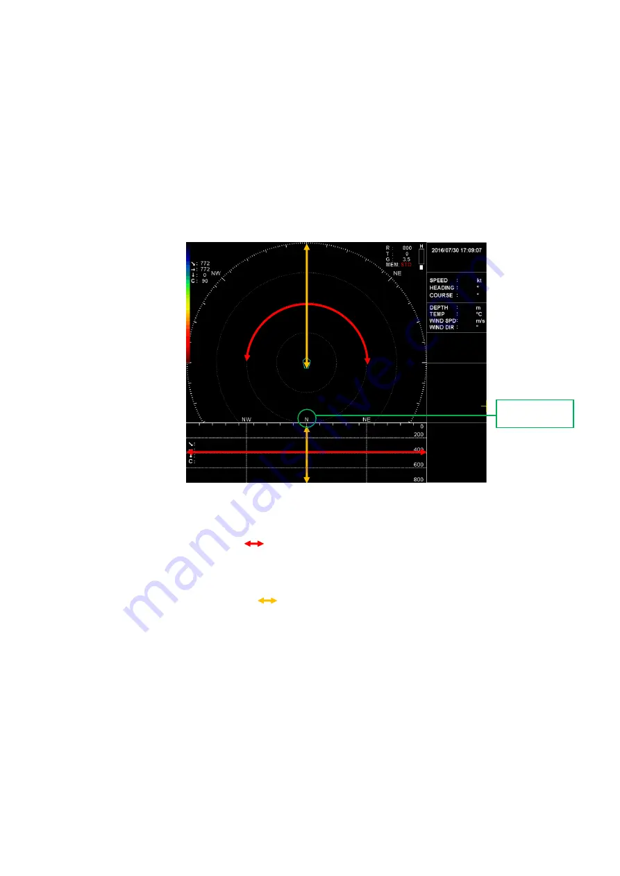
The Orthogonal screen draws a horizontal sonar picture displayed on a concentric circle.
The horizontal sonar picture in the bearing direction is drawn on the horizontal axis and
that in the distance or depth direction is drawn on the vertical axis.
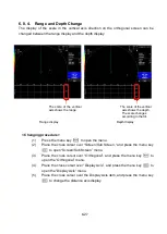
When the drawing area is 180°
The sonar picture (the red arrow
area) in the bearing direction with the center on the
bow bearing is displayed in the horizontal axis direction of the orthogonal screen. The
center of the horizontal axis of the orthogonal screen is the bow bearing.
A sonar picture (the yellow arrow
area) in the distance direction from the ship is
displayed in the vertical axis direction of the orthogonal screen.
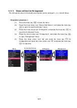
Note: While the orthogonal screen is being displayed, the off-center and
over-range displays are disabled.
Bow bearing
Summary of Contents for KCS-5200
Page 1: ...Model KCS 5200 Color Scanning Sonar Operation Manual Ver 1 48 E Rev 0...
Page 2: ......
Page 14: ......
Page 22: ...2 4...
Page 28: ...3 6...
Page 50: ...5 16...
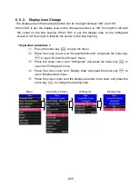
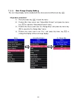
Page 78: ...6 28 Menu Screen Sub Screen Orthogonal Display Axis...
Page 80: ...6 30...
Page 84: ...7 4...
Page 90: ...8 6...
Page 106: ...9 16...
Page 116: ...10 10...