


9-4
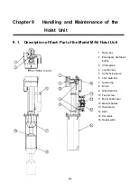
9. 2. Relay Box
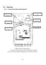
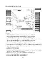
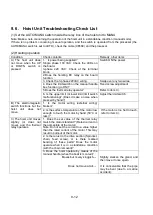
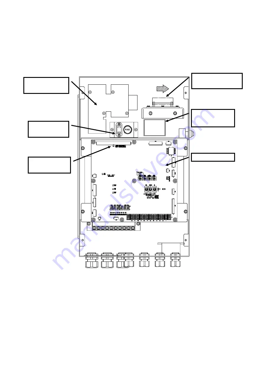
9. 2. 1. Name of Each Part of the Relay Box
*1 Differs according to the applicable hoist.
*2 The cable is connected only in the case of a half scanning sonar system.
*3 In the case of a system that has a stabilizing function, an inclinometer is installed.
Inclination sensor (IMU)
(*3)
Reverse rotation
prevention relay
HPC-2S PCB
Electromagnetic switch
thermal relay (*)
Service wall outlet
(100 VAC)
Flat cable connector
(*2)
Summary of Contents for KCS-5200
Page 1: ...Model KCS 5200 Color Scanning Sonar Operation Manual Ver 1 48 E Rev 0...
Page 2: ......
Page 14: ......
Page 22: ...2 4...
Page 28: ...3 6...
Page 50: ...5 16...
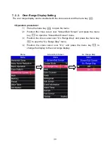
Page 78: ...6 28 Menu Screen Sub Screen Orthogonal Display Axis...
Page 80: ...6 30...
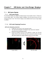
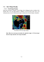
Page 84: ...7 4...
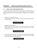
Page 90: ...8 6...
Page 106: ...9 16...
Page 116: ...10 10...


