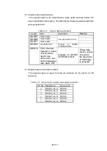
Ⅲ
-IV-20
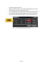
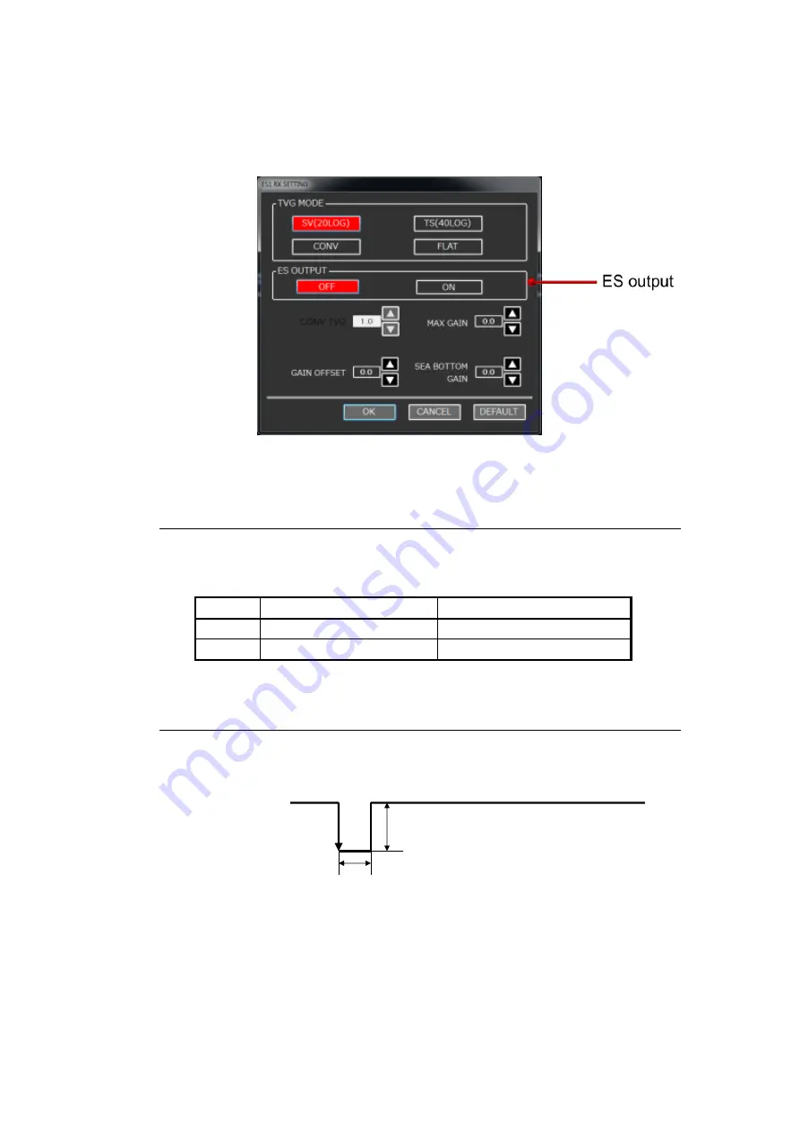
(2) Soft settings
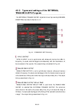
When the ES output from the dialog box for the receiving settings
indicated in Section 3-2-4 is set to ON, the ES data is output.
Fig. 4-16
Receiving setting dialog window
4-6-2
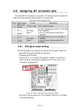
Connecting the ES trigger output signals
The ES trigger signal is output from pin Nos. 1/2 of connector J51.
Table 4-21 Connector J51ES trigger output signal connection table
Pin No Signal name
Signal level
1
TRG_OUT
Level output
2
DGND
GND
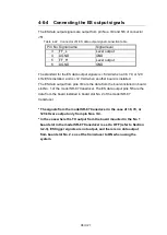
4-6-3
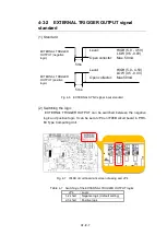
Standard for ES trigger output signals
The standard for the ES trigger output signals is shown below.
Fig. 4-17
ES trigger output signal standard
Level
:
HIGH(5V
±
0.5V)
LOW(0V
±
0.5V)
Same as TX pulse
ES trigger output
signal (negative
logic)
Summary of Contents for KSE-310
Page 1: ...KSE 310 TYPE FISH SIZING ECHO SOUNDER Instruction Manual Ver 5 04E SONIC CORPORATION ...
Page 2: ... MEMO ...
Page 163: ...III 153 ...
Page 166: ...III 156 3 2 1 CURSOR CONTROL This is described in Section 2 9 ...
Page 186: ...Ⅲ IV 14 Fig 4 13 NET DEPTH Display Method dialog ...
Page 196: ......

