V-1
5-2
Hardware problems: examples and
measures
This chapter describes problems that may occur before checking by the self-
monitor described in Section 3-1-6-2.
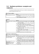
[RC-21 Type Controller]
Item
Measure
The power key fails to turn red.
(1) Check that the power cable of PRC-63 Type Computing Unit
is connected.
(2) Check that the connection to the RC connector of PRC-63
Type Computing Unit is not loose.
[Indicator]
Item
Measure
Although power is ON, no picture is
displayed.
(1)
If the power lamp of the indicator is red, the RGB cable
may not be connected, or PRC-63 Type Computing Unit
may not be activated.
(2)
Check whether the RGB cable is correctly connected to
the indicator and PRC-63 Type Computing Unit.
(3)
Check that the power key of RC-21 Type Controller is
turned ON in green color to make sure PRC-63 Type
Computing Unit is activated.
(4)
If the power key of RC-21 Type Controller is red, press the
power key to turn ON.
(5)
If the power key is not red, refer to the measures described
in the above [RC-21 Type Controller].
(6)
Check whether the values of brightness and contrast are
too low.
(7)
Check whether the fuse of the indicator is blown.
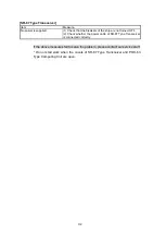
[PRC-63 Type Computing Unit]
Item
Measure
Although the power key of RC-21
Type Controller is ON in green,
no power is supplied.
(1)
Turn the power key of the RC-21 Type Controller ON again.
(2)
SR-87 Type Transceiver may not be activated. Referring to
[SR-87 Type Transceiver] on the next page, activate SR-87
Type Transceiver.
(3)
When the battery inside the model PRC-63 runs down, the
system can no longer start. In such a case, contact your
local dealer or our serviceman to have the battery replaced.
When the measurement icon is
activated, “SR
COMMUNICATION ERROR
CHECK CONNECTION” is
displayed.
(1)
Check that the CB-25 cable connector between PRC-63
Type Computing Unit and SR-87 Type Transceiver is not
loosened.
(2)
If it is loosened, turn OFF the power, and connect it again
before using.
Summary of Contents for KSE-310
Page 1: ...KSE 310 TYPE FISH SIZING ECHO SOUNDER Instruction Manual Ver 5 04E SONIC CORPORATION ...
Page 2: ... MEMO ...
Page 163: ...III 153 ...
Page 166: ...III 156 3 2 1 CURSOR CONTROL This is described in Section 2 9 ...
Page 186: ...Ⅲ IV 14 Fig 4 13 NET DEPTH Display Method dialog ...
Page 196: ......

