
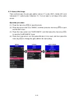

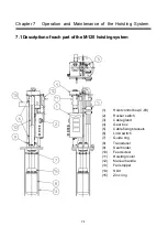


7-9
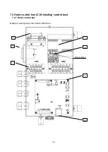
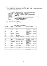
(xiii) Jumper pin for determining contact signal output operation
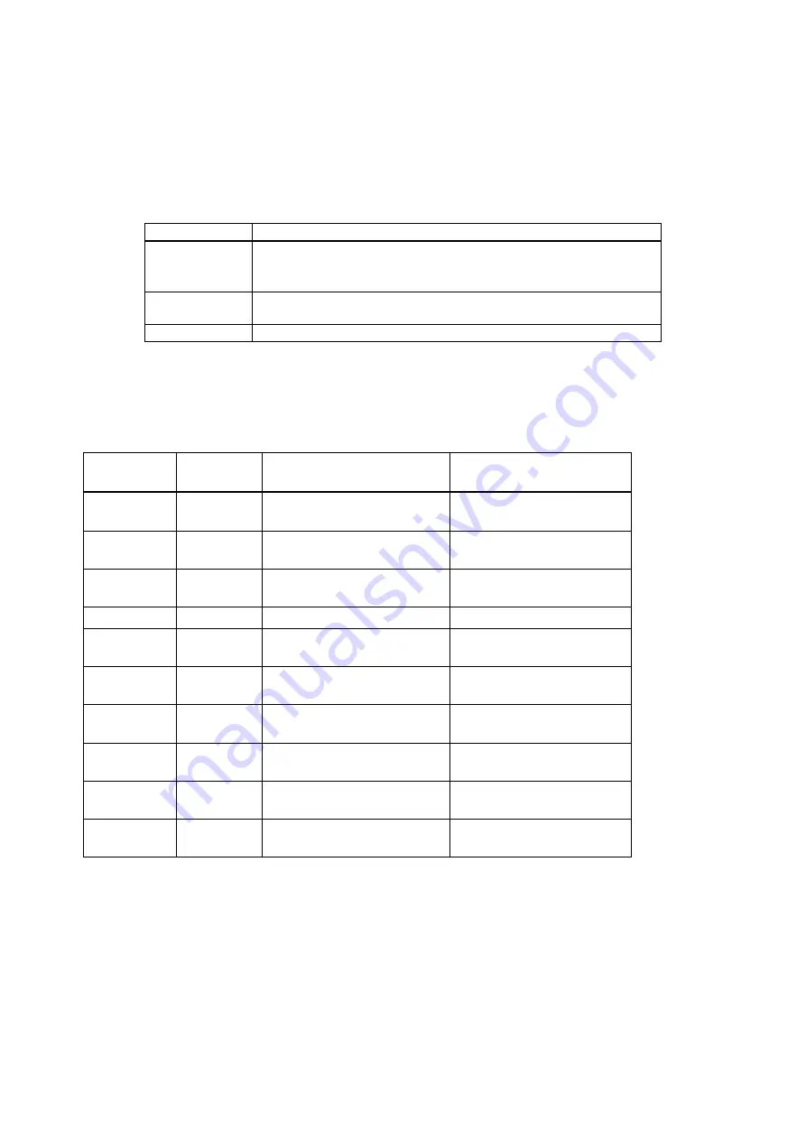
In JP1 setting, the operation of the contact signal output is determined. Please
change the setting as necessary.
Table: JP1 setting (operation of the contact signal output)
JP1 setting
Operation of the contact signal output
1-2 shortcut
(before
shipment)
The contact is ON when the hoisting system is at the
upper limit.
2-3 shortcut
The contact is ON when the hoisting system is in
operation (ascending/descending).
Open
The contact is always OFF.
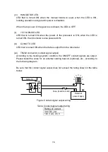
(xiv) TB201 connector (CB561)
Connector for connecting the CB561 cables
Table: TB201 pin assignment
TB201
CB561
wire color
Signal name
Signal direction
1
Brown
HOLD
Processor → hoisting
system
2
Red
FALL
Processor → hoisting
system
3
Orange
BUZZER
Processor → hoisting
system
4
Yellow
GND_ISO
-
5
Green
LOWER_LIMIT_ISO
Hoisting system →
processor
6
Blue
UPPER_LIMIT_ISO
Hoisting system →
processor
7
Light blue CLINO
Processor → hoisting
system
8
Gray
CLINO_ON_OFF−
Processor → hoisting
system
9
White
CLINO_422A
Hoisting system →
processor
10
Black
CLINO_422B
Hoisting system →
processor
Summary of Contents for SCS-60
Page 1: ...Model SCS 60 Scanning Sonar Operation Manual Ver 5 00E Rev 0...
Page 2: ...MEMO...
Page 12: ...x MEMO...
Page 16: ...1 4 MEMO...
Page 32: ...4 6 MEMO...
Page 50: ...5 18 MEMO...
Page 70: ...6 20 MEMO...
Page 86: ...7 16 MEMO...
Page 94: ...8 8 MEMO...