background image

OPTIONS

The following options and accessories are available for the H520E and

H540E systems.

1.

FOOT SWITCH

for remote activation. (When foot switch actuation is

used, the trigger handle is removed from the hand gun housing.)

2.

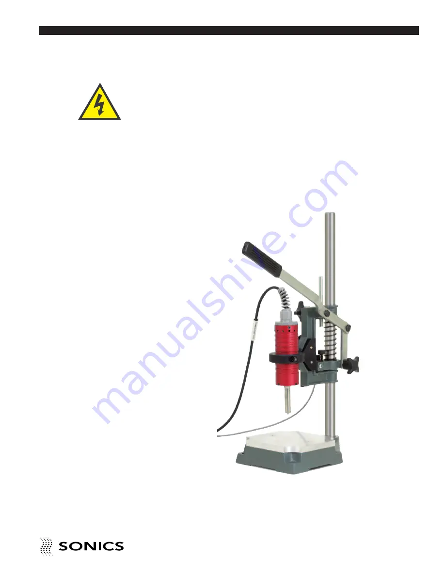
MANUAL ARBOR PRESS,

available with foot switch or cam actuation,

is designed for assembling parts where production volume does not

justify automated equipment. The press provides a more controlled

motion of the welder than is possible by just holding the hand gun,

resulting in more consistent assemblies.

MANUAL PRESS

Always turn off the

power supply before

installing or removing

the foot switch cable.

I N S T R U C T I O N M A N U A L • M O D E L H 5 2 0 E / H 5 4 0 E

17

• • • • • • • • • • • • • • • • • • • • • • • • • • • • • • • • • • • • • • • • • • • • • • • • • • • • • • • • • • • • • • • • • • • • • • • • • • • • • • • • • • • • • • • • • • • • • • • • • • • • • • • • • • • •

info@qoovia-hk.com


www.qoovia-hk.com

WWW.QOOVIA-HK.COM

Summary of Contents for H520E

Page 1: ...RYLD RUSRUDWLRQ RQJ RQJ LPLWHG Hong Kong Office 15B Granville House 41C Granville Road T S T Kowloon Hong Kong Dongguan Office 6 Hang No 17 Heng Xin Road Heng Gang Tou Xin An Qu Chang An Dongguan Guangdong China 523882 Tel 86 0769 8532 0321 Fex 86 0769 8532 0145 Tel 86 00852 61717217 81463719 Fax 86 00852 81479859 W W W Q O O V I A H K C O M ...

Page 2: ...ctions 11 Cable Connections 12 Key Components 13 Tip Assembly CV55 14 Tip Replacement CV55 14 Horn Assembly CVG54 Only 14 Tip Replacement CVG54 15 Tip Specifications 16 Options 17 Information contained in this manual is subject to change without notice Sonics Materials Inc is not responsible for any typographic errors Sonics Materials Inc 2009 Printed in U S A Part No 381 0035 Rev 00 11 09 હ 䲙 佭 䰤...

Page 3: ...verload Protection 26 Keypad Security 27 APPLICATIONS STAKING 28 Standard Flared Stake 28 Spherical Stake 29 Hollow Stake 29 Knurled Stake 29 Flush Stake 30 APPLICATIONS SPOT WELDING 31 Ordering Information 31 APPLICATIONS ULTRASONIC INSERTION 32 MAINTENANCE 34 Cleaning Instructions 34 Repairs Service 34 WARRANTY 35 Limitation of Warranty 36 APPENDIX 38 2 I N S T R U C T I O N M A N U A L M O D E ...

Page 4: ...nected to the hand gun Never secure anything to the front driver the tip or the horn Never touch a vibrating horn If air cooling the converter always use dry compressed air Hearing protection is highly recommended It is recommended that a sound abating enclosure or ear protection be used when operating the Ultrasonic Processor Do not modify horn configurations Do not affix any device to any portio...

Page 5: ...HOCK HAZARDOUS VOLTAGE CAUTION RISK OF DANGER REFER TO USER MANUAL WARNING or CAUTION Where you see the alert symbols and or WARNING or CAUTION heading strictly follow the warning instructions to avoid personal injury or equipment failure info qoovia hk com www qoovia hk com W W W Q O O V I A H K C O M ...

Page 6: ...ures up to 31ºC decreasing linearly to 50 relative humidity to 40ºC Other For indoor use only Converter CV 55 CV 54 Weight 1 5 lbs 0 68 Kg 1 5 lbs 0 68 Kg Dimensions 7 6 L x 1 9 Dia 6 3 L x 1 9 Dia 93 mm x 48 3 mm with standard tip 160 mm x 48 3 mm without horn Horn Materials Titanium Titanium or aluminum Power Supply Operational Input Voltage 115 230 V 10 50 60 Hz Rated Voltage Current 115 230 V ...

Page 7: ...cannot incorporate these changes immediately into printed manuals Hence your manual may contain new change information Change information if any is located in the Appendix We reserve the right to make any changes in the design or construction of our equipment at any time without incurring any obligation to make any change whatsoever in units previously delivered The technical data and schematics i...

Page 8: ...e such external evidence of loss or damage may result in the carrier s refusal to honor a damage claim The form required to file such a claim will be supplied by the carrier CONCEALED LOSS OR DAMAGE Concealed loss or damage means loss or damage which does not become apparent until the merchandise has been unpacked The contents might have been damaged in transit due to rough handling even though th...

Page 9: ...BLY WHAT IS ULTRASONICS Ultrasonics refers to vibrational waves with a frequency above the human audible range which is usually above 18 000 cycles per second Hz PRINCIPLE OF ULTRASONIC ASSEMBLY The basic principle of ultrasonic assembly involves conversion of high frequency electrical energy to high frequency mechanical energy in the form of reciprocating vertical motion which when applied to a t...

Page 10: ...ations Transforms ultrasonic electrical energy to ultrasonic mechanical vibrations Contacts and transfers vibrational energy to plastic part Converter Horn Replaceable Tip Ultrasonic Vibrations Power Supply Generator Hand Gun I N S T R U C T I O N M A N U A L M O D E L H 5 2 0 E H 5 4 0 E 9 info qoovia hk com www qoovia hk com W W W Q O O V I A H K C O M ...

Page 11: ...al vibrations TIP HORN The tip horn is a tuned component of the system which comes in contact with the parts to be assembled The tip horn 1 transfers the ultrasonic vibrations produced from the converter to the parts being welded and 2 applies necessary force to the assembly while the material resolidifies AMPLITUDE The peak to peak excursion of a horn at its output face 10 I N S T R U C T I O N M...

Page 12: ...to keep surrounding air within acceptable ambient temperature limits Periodically check the ventilation grille and clean as necessary ELECTRICAL CONNECTIONS When making the initial electrical connections make sure the power is disconnected and follow these precautions 1 Do not strain or kink the cables When going around corners allow as wide a bend as possible Do not run the cables parallel to any...

Page 13: ...ve been made the power supply is ready for operation Also located at the rear of the power supply are the following 4 Foot switch jack connects foot switch cable to enable remote actuation 5 Fuses 120V 15A slo blo 230V 8A slo blo 15 15 FOOTSWITCH NW SONICS MATERIALS INC 50 CHURCH HILL RD NEWTOWN CT USA OUTPUT Make sure the ON OFF switch is in the OFF position and the power supply line cord is not ...

Page 14: ...ith 2 hand gun options 20 kHz CV55 and 40 kHz CVG54 POWER SUPPLY HAND GUN TRIGGER SWITCH CV55 CVG54 HORN TIP TIP HAND GUN I N S T R U C T I O N M A N U A L M O D E L H 5 2 0 E H 5 4 0 E 13 info qoovia hk com www qoovia hk com W W W Q O O V I A H K C O M ...

Page 15: ...hreaded stud and hole Check that the stud is tight see recommended torque requirements on page 13 2 Hand assemble the converter and horn together using open ended wrenches as shown below Tighten securely Do not force or overtighten NOTE Never remove or install a tip by holding the hand gun case or rotating the tip with only one wrench as this may cause damage to the booster and or converter CVG54 ...

Page 16: ... TIP REPLACEMENT CVG54 1 Clean the mating surfaces as well as the threaded stud and hole Check that the stud is tight See recommended torque requirements below 2 Hand assemble the tip to the horn using open ended wrenches as shown below and tighten securely Do not force or overtighten I N S T R U C T I O N M A N U A L M O D E L H 5 2 0 E H 5 4 0 E 15 info qoovia hk com www qoovia hk com W W W Q O ...

Page 17: ...om faced tips are available Refer to the various tables under staking spot welding and insertion descriptions on pages 26 31 for lists of standard threaded tips For custom tips call our Sales Department at 203 270 4600 STAKING INSERTING SPOT WELDING FLAT KNURLED 16 I N S T R U C T I O N M A N U A L M O D E L H 5 2 0 E H 5 4 0 E info qoovia hk com www qoovia hk com W W W Q O O V I A H K C O M ...

Page 18: ...ctuation is designed for assembling parts where production volume does not justify automated equipment The press provides a more controlled motion of the welder than is possible by just holding the hand gun resulting in more consistent assemblies MANUAL PRESS Always turn off the power supply before installing or removing the foot switch cable I N S T R U C T I O N M A N U A L M O D E L H 5 2 0 E H...

Page 19: ...duction rate clamshell packages 4 PISTOL GRIP for more ergonomic handling of the hand gun in specialized applications STAPLER PISTOL GRIP 18 I N S T R U C T I O N M A N U A L M O D E L H 5 2 0 E H 5 4 0 E info qoovia hk com www qoovia hk com W W W Q O O V I A H K C O M ...

Page 20: ...s that is being delivered to the welder see 3 below 3 LOAD METER SCALE from 0 to 100 which in conjunction with vertical line indicators on LCD display shows the running power bar graph at bottom of display and peak power single vertical line at top of display during the weld Peak power is reported as Pmax after the cycle see page 21 4 TIME key which allows selection and display of time settings an...

Page 21: ...condition Red LED in upper left corner indicates an overload condition exists Refer to page 24 for complete information 10 0 9 NUMERIC KEYPAD which allows input of numeric data by pressing the keys 11 CLEAR key which clears the preceding entry when pressed 12 ENTER REVIEW key which serves to enter data into the system and or to display data or parameters on the LCD screen KEYING IN PARAMETERS To m...

Page 22: ...depressing the TEST button check the display Make sure the bar graph indicator on the display a series of vertical lines that register to the 0 to 100 load meter scale see example below does not exceed 20 During the testing process keep in mind that the ultrasonics are only activated as long as the TEST button is depressed once you release the TEST button ultrasonics is terminated A bar graph indi...

Page 23: ...utside of the specified tolerance limits The screen will indicate whether alarms occurred in Time or Energy If there are no alarms dashes will display If there are alarms an L for Low limit indicating that the low limit was violated and or an H for High limit indicating that the high limit was violated will display by the applicable mode time or energy Once another new cycle is begun the system wi...

Page 24: ...ivered and vice versa The start up ready screen which shows the last weld information will show a flashing sec or J to indicate which setting was achieved first and thereby terminated the weld cycle In the example above if the weld time of 2 seconds is reached before 2000 joules have been delivered the ready screen will display 02 00 sec with the sec flashing along with whatever energy was deliver...

Page 25: ... next screen displays Time Limit Low sets the low time alarm examination point as a tolerance limit A time alarm will be triggered if the actual weld time is less than this value The time low alarm will show on the Alarm Screen display and will be indicated by a flashing LED on the Time key By specifying values for this limit and the Time Limit High a weld time window is created that defines a goo...

Page 26: ... the Energy Limit High a weld energy window can be created in which a good weld can occur If no alarms are triggered the weld cycle occurred within the designated energy limits Energy Limit High sets the high energy alarm examination point see Limit Low above An energy alarm will be triggered if the actual weld energy is greater than this value The energy high alarm will show on the Alarm Screen d...

Page 27: ... methods If an ultrasonic overload condition exists simply press the O L Reset key to reset the system If a shock protection condition caused the overload the system cannot be reset with the O L Reset key The system must be powered down using the ON OFF switch and the cable hand gun connection problem s fixed before turning the power supply back on There is a ground fault circuit for shock protect...

Page 28: ...ard thereby preventing unauthorized cancellation or adjustment To activate the security feature press and hold the numeral 7 key on power up When the keypad is secured in this manner any attempt to change or enter parameters will result in the following message being displayed on the LCD screen KEYBOARD LOCKED info qoovia hk com www qoovia hk com W W W Q O O V I A H K C O M ...

Page 29: ... from the horn forms a head to a shape determined by the horn tip configuration When the vibrations stop the plastic material solidifies and the dissimilar materials are fastened together With staking tight assemblies are possible because mating parts are clamped under pressure of the horn until the rivet head solidifies There is no elastic recovery as is the case with heat staking or cold forming...

Page 30: ...on the opposite side of the component and enables the parts to be reassembled with self taping screws should repair and disassembly be necessary KNURLED STAKE The knurled stake is used in applications where appearance and strength are not critical Since alignment is not an important consideration the knurled stake is ideally suited for high volume production and is often recommended for use with a...

Page 31: ...TIP CODE LETTER Plastic Boss Solid Boss Conical Boss Diameter Flare Head Spherical Head Hollow inches mm High Profile Low Profile High Low Boss Tip Size Stud Height Tip Size Stud Height Profile Profile 1 32 0 793 A 050 G 019 AA GG 1 16 1 587 B 100 H 0375 BB HH 3 32 2 381 C 150 I 056 CC II 1 8 3 175 D 200 J 075 DD JJ R 5 32 3 969 E 250 K 094 EE KK S 3 16 4 762 F 300 L 112 FF LL T STAKING BEFORE AFT...

Page 32: ...and forms a permanent molecular bond Large thermoplastic parts and applications with hard to reach joining surfaces can easily be welded together using an ultrasonic spot welder and standard replaceable tips STANDARD THREADED TIPS FOR SPOT WELDING ORDERING INFORMATION Specify tip required using code letter Example Spot weld tip SA indicates a tip used for spot welding 1 32 thick material BEFORE AF...

Page 33: ...s flutes or undercuts of the inserts and when the vibrations terminate the plastic resolidifies and the insert is securely encapsulated in place Inserts can be ultrasonically installed in most thermoplastics Ultrasonic insertion provides the high performance strength values of a molded in insert while retaining all of the advantages of post molded installation Some of the advantages of ultrasonic ...

Page 34: ...0 0 088 0 078 6 32 0 106 0 096 8 32 0 133 0 123 10 24 0 147 0 137 10 32 0 160 0 150 1 4 20 0 200 0 190 1 4 28 0 211 0 201 5 16 18 0 262 0 252 METRIC 2 5 x 0 45 0 079 0 069 3 x 0 50 0 097 0 087 3 5 x 0 60 0 114 0 104 4 x 0 70 0 129 0 119 5 x 0 80 0 165 0 155 6 x 1 00 0 195 0 185 8 x 1 25 0 265 0 255 INSERTING info qoovia hk com www qoovia hk com W W W Q O O V I A H K C O M ...

Page 35: ...system in need of repair be sent back to the factory with a written description pertaining to the nature of the problem Always contact the factory for return authorization before shipping any instrument Include date of purchase model number and serial number For units not covered by the warranty a purchase order should be forwarded to avoid unnecessary delay Care should be exercised to provide ade...

Page 36: ...e without charge if failure occurs within the warranty period Ultrasonic plastics welding horns constructed of steel are guaranteed against defects for a period of ninety days from date of shipment Sonics will repair or replace a cracked or defective steel horn once at a charge of 50 of the original purchase price if failure occurs within the warranty period Ultrasonic metal welding horns construc...

Page 37: ...n will cause damage to the equipment and may result in warranty nullification Sonics assumes no responsibility for converters horns or fixtures not supplied by Sonics or for consequential damages resulting from their usage Ultrasonic converters showing signs of excessive heat or contamination such as but not limited to oils and moisture are not covered by this warranty Warranty does not apply to u...

Page 38: ...ther warranties either express implied or statutory Sonics neither assumes nor authorizes any person to assume for it any other obligation or liability in connection with the sale of its products Sonics hereby disclaims any warranty or merchantability or fitness for a particular purpose No person or company is authorized to change modify or amend the terms of this warranty in any manner or fashion...

Page 39: ... 38 I N S T R U C T I O N M A N U A L M O D E L H 5 2 0 H 5 4 0 APPENDIX DB9 I O CONNECTIONS DIAGRAM info qoovia hk com www qoovia hk com W W W Q O O V I A H K C O M ...

Reviews: