Technical Specification
Sonifex HY-03 User Handbook
9
Technical Specification
HY-03 Connection Details
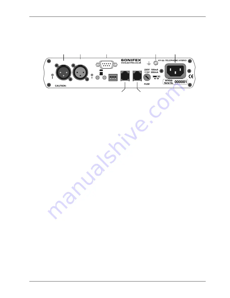
All of the connections are located on the rear of the HY-03 :
Figure 3-1 : HY-03 Rear Panel Connections
Line Output
The line output is an XLR 3 pin male connector (XLR-3-32, 50 ohm balanced floating).
Pin 1 : Screen
Pin 2 : Phase
Pin 3 : Non-phase
Mic/Line Input
The line input is an XLR 3 pin female connector (XLR-3-31, 10k ohm balanced floating).
Pin 1 : Screen
Pin 2 : Phase
Pin 3 : Non-phase
Remotes
The remote connector is a 9-way female (socket) ‘D’ type. To remotely divert, connect pin 1 to pin 2. Pin 3 su15V
with reference to pin 4. The remotes can act as momentary or latching depending on the setting on the rear panel of the
unit.
Pin 1 : Divert switch (Line Connect)
Pin 2 : Common
Pin 3 : Lamp
Pin 4 : Common
The remote lamp tally mimics the front panel line connect switch lamp, i.e. it flashes when ringing and is on when the line
is held.
Telephone Handset
This is the connection for a telephone handset and is an RJ11 socket. There is a converter supplied with the HY-03 for
accepting a standard BT605A telephone plug.
Telephone Line
This is the telephone line connection and is an RJ11 6/4 socket. Two cables are supplied with the unit, to connect this
either to a UK BT line jack socket, or an RJ11 socket. The telephone line is connected via the white and red wires on the
connector (on a BT plug, the latch is adjacent to Pin 6).
Pin 1 : N/C
Pin 2 : Earth recall (Green wire)
Pin 3 : Telephone line A (White wire)
Pin 4 : Telephone line B (Red wire)
Pin 5 : Ringer (Blue wire)
Pin 6 : N/C
Mains Input
The power supply is connected via an IEC Connector (CEE22, 230V - 50Hz, or 115V – 60Hz).
Disconnect the mains supply before removing the equipment covers.
HANDSET
REN = 1
LINE
MIC/LINE
INPUT
This product must be earthed
REMOTES
SETTINGS
PERMANENT
MOMENTARY
OUTPUT
115V - 230V
MIC
LINE
MIC
LEVEL
OUTPUT
LEVEL
Telephone
Handset
Telephone
Line
Line
Output
Mic/Line
Input
Mains
Input
Protective
Earth Terminal
Remotes


