Circuit Description & Controls Page 2-3
HY02 Digital TBU User's Guide
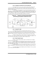
2.2.2. Telephone Line, Barrier and Transformer
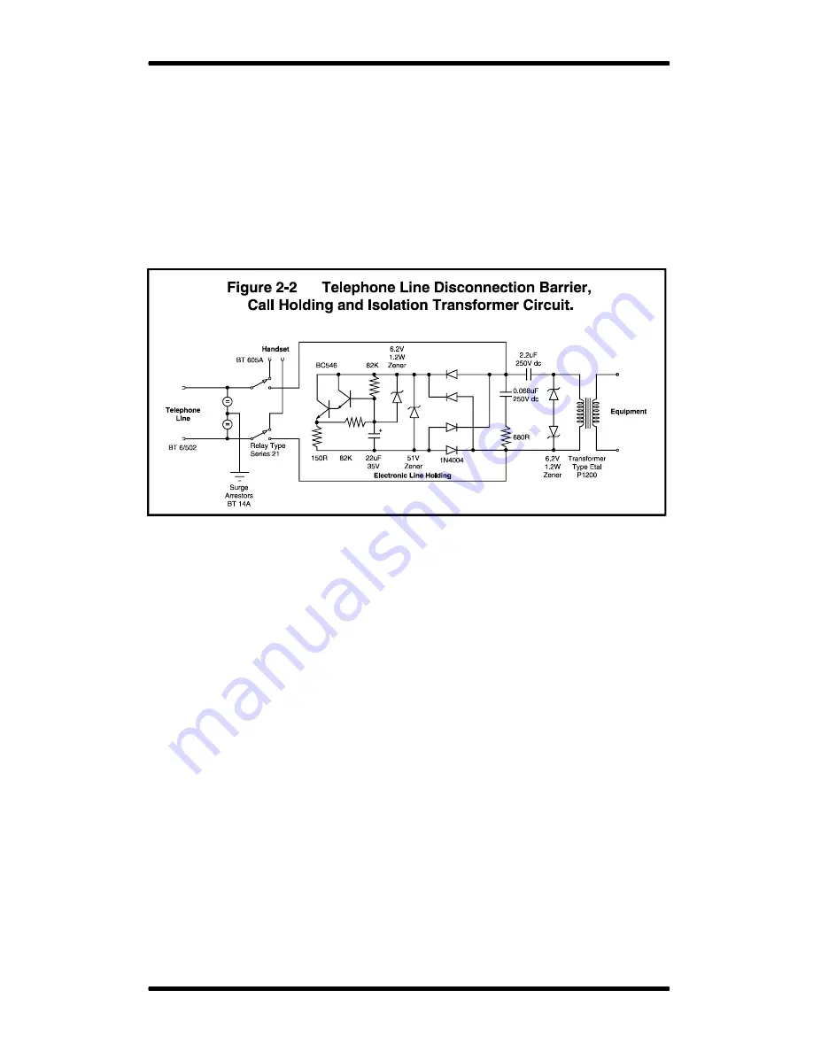
The telephone line port is a two wire connection into the apparatus through a line
cord and jack BT 6/502, with a surge arrestor BT 14A from the A and B wires to earth. The line
connection is switched by a divert switch and relay between the hybrid unit and the handset connected
through a BT 605A connector.
The line is held, on the equipment side, by an electronic line holding circuit Q29,
Q28 and Q27, the A leg fed through a 2.2 uF 250V d.c. blocking capacitor to the line transformer TR1
(ETAL P1200). A pair of zener diodes arranged in a back to back configuration across the primary of
the line transformer, are arranged to act as overvoltage protection. The line transformer is designed to
meet BS 6305. Figure 2-2 shows a schematic diagram of this part of the ciruitry.
2.2.3. Output Circuits
The output from the codec Q36 is presented at balanced line level via a servo
balanced output stage. Amplifier Q2d and transistors Q31 and Q32 form a low impedance push-pull
amplifier driving the output balancing transformer TR3. The diodes D21 and D22, R72 and R71 form a
bias chain for the drive transistors. The input at Q2d is filtered by R79 and C43 a simple low pass
filter.
The balanced output at TR3 is less than 50 ohms at the frequencies used and has a
high common mode rejection. The output signal at TR1 consists of the telephone line signal only, with
the local clean feed content nulled out to better than -69dB ref +8dB peak output.
2.2.4. Divert Switch Logic
With the system unenergised the logic connects the telephone line to the handset
through relay RL1 relaxed contacts.
The logic circuits Q1a and Q1b change the state of the relay contacts via Q17, Q36,
Q1f and Q5, diverting the telephone line to the equipment, when the divert switch is activated. The
logic is edge triggered and will accept remote commands. This logic also drives the indicator lamp at
the switch and remote lamp contacts.
The logic holds the relay in the divert condition until either power is removed or the
switch is operated again. K break and dial hang up tone will also untrigger the latch when required to
do so.
A signal from the logic operates input muting when the handset is in use preventing
spurious output signals at the equipment.
Summary of Contents for HY02 DIGITAL
Page 14: ...Page 1 8 Introduction Installation HY02 Digital TBU User s Guide This page deliberately blank ...
Page 16: ...Page 2 2 Circuit Description Controls HY02 Digital TBU User s Guide ...
Page 22: ...Page 2 8 Circuit Description Controls HY02 Digital TBU User s Guide ...
Page 25: ...Page 0 Index HY02 Digital TBU User s Guide ...
Page 27: ...HY02 Digital TBU User s Guide ...

