Circuit Description & Controls Page 2-7
HY02 Digital TBU User's Guide
2.3. Alignment Controls
The following alignment controls and jumpers are provided within the equipment for
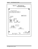
setting the general operating parameters. For the position and layout of the preset alignment controls,
see Figure 2-3, overleaf. For normal operation of the equipment, these controls will not need to be
altered.“Set” or “Enabled” implies that the jumper is on.
Do not adjust these settings without consulting a technical information file.
2.3.1. Jumpers
JP1
Controls whether the Remotes connections are actuated by momentary
or permanent contacts. Set over 1 & 2 for momentary. Set over 2 & 3
for
permanent.
JP2
Set for line disconnect ( default ). If the caller hangs-up, this will drop
the line off using K-break.
JP3
Set for auto answer. The ringing detector circuitry must be fitted.
JP4
Factory set on pins 2 & 3 - do not adjust.
JP5
Factory unset - do not adjust.
JP6
Factory set on pins 1 & 2 - do not adjust.
JP7
Link for instant reset.
JP8
Controls disconnect tones : Set for single tone, unset for dual tone
(UK).
JP9
Controls disconnect tones : Set for pulse tone ( Belgium, France ), unset
for continuous disconnect ( UK ).
JP10
Controls disconnect tone burst : Set for long burst ( 4 secs ), unset for
short ( 2 secs ) disconnect tone burst ( UK ). It is the length of time that
the line tone has to be present before the automatic disconnect operates.
JP11
Set for dial tone detect ( hang up tone ). If JP2 is connected and the K-
break has failed, this will automatically hang the line up.
JP12
Line connect enable. This is factory set and should not be adjusted.
JP13 Not
used
2.3.2. Preset Potentiometers
RV1
This sets the frequency of the primary 440 Hz disconnect tone. Range
is
250 - 550 Hz.
RV2
This sets the frequency of the secondary 350 Hz disconnect tone. Range
is 250 - 550 Hz.
RV3
This sets the number of rings before operation of the ringing detector
between 1 and 5 rings.
2.3.3. LEDs
LD1
Status LED provides error message information ( See Section 2.2.8 ).
LD2
Transmit LED is on whenever transmitting.
LD3
Receive LED is on whenever receiving.
Summary of Contents for HY02 DIGITAL
Page 14: ...Page 1 8 Introduction Installation HY02 Digital TBU User s Guide This page deliberately blank ...
Page 16: ...Page 2 2 Circuit Description Controls HY02 Digital TBU User s Guide ...
Page 22: ...Page 2 8 Circuit Description Controls HY02 Digital TBU User s Guide ...
Page 25: ...Page 0 Index HY02 Digital TBU User s Guide ...
Page 27: ...HY02 Digital TBU User s Guide ...

