2. Net-Log Hardware
Sonifex Net-Log User Handbook
11
N
ET
-L
OG
H
ARDWARE
2
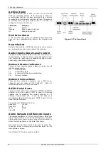
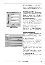
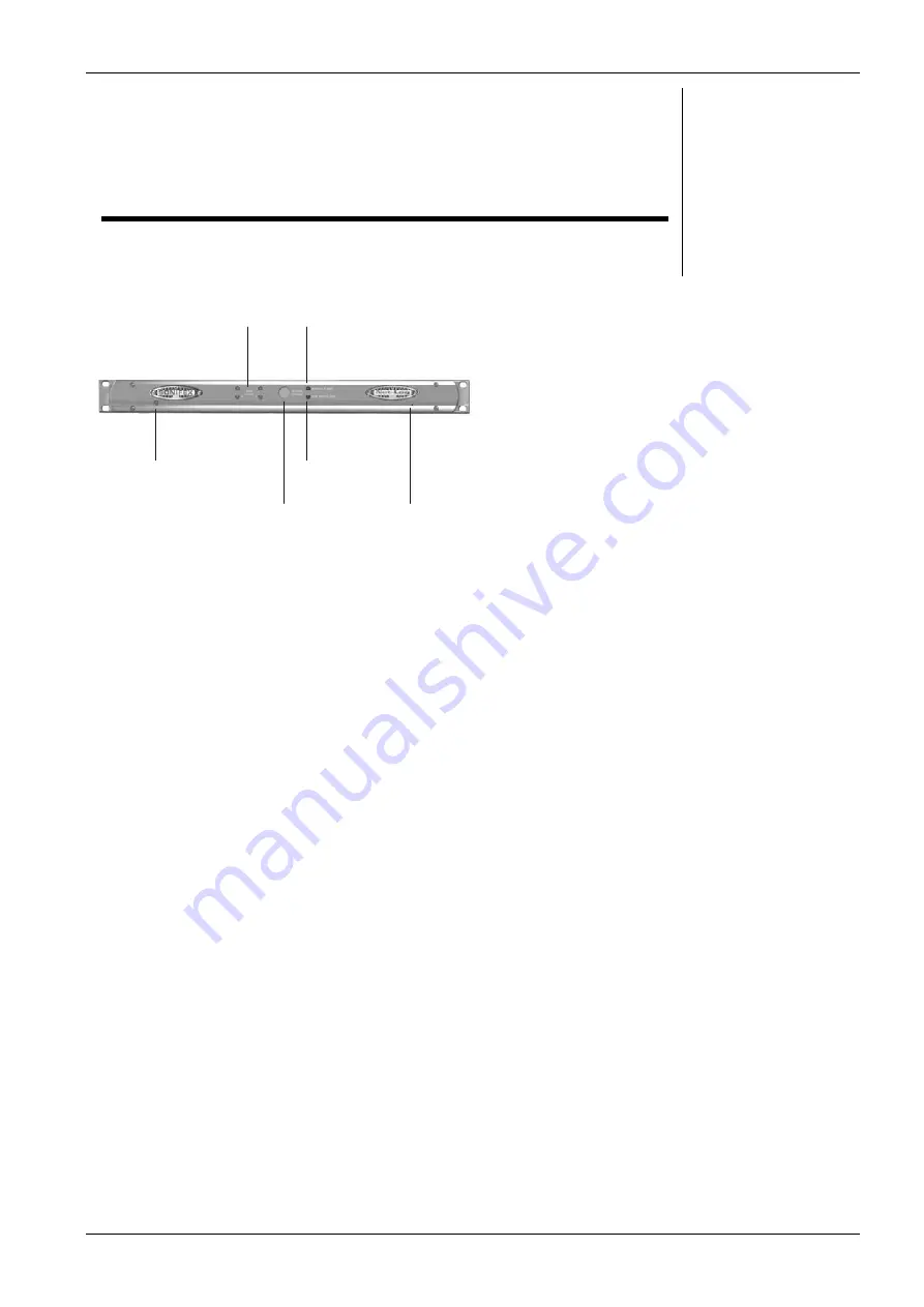
Figure 2.1 The Front Panel
Physical Description
The logger is housed in a 1U high 19” rack mount box.
The front panel is sprayed with a green to purple “flip”
colour, which also has a fish-scale overlay. There are
chrome plated panel inserts for the fan inlet/outlet with
domed labels for the “Sonifex” and “Net-Log”.
Power
The unit is powered via an IEC filtered input for 95 – 265V
supply at 47–63Hz, peak 60W, 30W average. There is an
external fuse for the mains input that is rated at 2A. We
recommend that the Net-Log is operated from an
uninterruptable power supply. It should be noted that the
record header is written regularly during the record
process so if the power fails the data lost will be limited.
At a bit rate of 192kbps this loss will be a maximum of 1
minute. Lower data rates will give proportionately greater
time loss.
Level Indicators
There are four tri-colour LED’s positioned on the front
panel indicating input levels for each individual channel:
Led State
Meaning
Off
Input level < -18dBu
Yellow
–18dBu < Input level < 0dBu
Green
0dBu < Input level < 12dBu
Red
Input level >12dBu
Record Control/Indicator
This backlit button gives an indication of what channels
are currently being recorded and can also be used to give
limited control over the recording. When pressed, the
button will flash indicating that a record start or stop has
been initiated and must be pressed again within three
seconds to confirm the action. The LED states and their
relative modes are shown below:-
Button State
Mode
Off
No channels recording
Fast flashing
Record Start/Stop initiated
Slow flashing
Some channels recording
On
All available channels recording
When the button is pressed, the Net-Log checks to see
which channels can be altered using this button (See
Options, Record Format options, Override Enabled). If
recording, a confirmed button press will stop the
recording. If not recording, a confirmed button press will
start the recording on enabled channels.
Level
Indicators
Power LED
Record
Control
Archive
Alarm
Disk Drive
Alarm
Reset
Switch
Summary of Contents for Net-Log
Page 1: ...Sonifex Net Log User Handbook...
Page 6: ...Contents Sonifex Net Log User Handbook...
Page 10: ...License Form Sonifex Net Log User Handbook 4...
Page 16: ...1 Introduction Sonifex Net Log User Handbook 10...
Page 24: ...3 Net Log Set up Installation Sonifex Net Log User Handbook 18...
Page 32: ...5 Recording Sonifex Net Log User Handbook 26...
Page 36: ...6 Playing Downloading Sonifex Net Log Win User Handbook 18...
Page 48: ...9 Serial Control Interface Sonifex Net Log Win User Handbook 30...
Page 56: ...11 The Administrator Sonifex Net Log Win User Handbook 38...
Page 62: ...13 Technical Specification Sonifex Net Log Win User Handbook 44...
Page 64: ...14 Glossary Sonifex Net Log Win User Handbook 46...


