9. Serial Control Interface
Single mic
This selection configures the associated channel to be
controlled by a single microphone. The microphone’s
identification number can be entered in the edit box.
Alternatively use the up/down arrows to select the
required identification number. The lowest microphone
number is 1 and the highest is 128.
Mic range
This selection configures the associated channel to be
controlled by a range of microphones. Activating any one
of the microphones in the specified range will start the
channel recording. The channel will only then stop
recording when all microphones in the range have been
deactivated. Again the lowest microphone number is 1 and
the highest is 128.
The settings for Single mic and Mic range can overlap such
that a microphone can control multiple record channels.
Once the required settings have been entered, press the
“Update” button, and they will be written to the Net-Log
shown in the Net-Log selector.
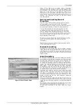
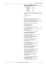
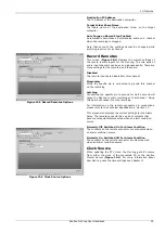
The cut list display in the Play screen in Net-Log-Win will
now show two additional columns: Mic and Name (see
Figure 9.3
). These new columns display the Mic number
and the Name of the speaker who initiated the recording.
When the Net-Log is powered up with the Televic CE2500
Interface selected, it waits to receive a synchronisation
command from the CE2500 before it will execute any
further commands. This is to ensure that if any of the
microphones are currently activated, and have been
previously associated with a record channel, recording is
started on the relevant channel. The synchronisation
commands are issued by the CE2500 every 5 seconds.
If an attempt is made to stop recording manually in Net-
Log-Win on a channel that is associated with an active
microphone, a warning message will be displayed in Net-
Log-Win.
An alternative method of controlling the recording can be
used when using the Televic CE2500 Interface. This is
done by utilising the closing contact controlled by the
AOP2500 Analog Output device. This contact is closed
when any of the microphones is activated and remains
closed until all microphones are deactivated.
By setting all available microphone options to “Disabled” in
the Control Options screen, serial control of record start
and stop is disabled. Note that the microphone number
and name are still recorded in this mode, but because only
one closing contact can be used by the AOP2500, only one
channel can be recorded, so the microphone number and
name are appended to the last recording.
The closing contact on the AOP2500 can then be used to
control the remote inputs on Net-Log. See “Record
Remotes” in Section 10 for more details on setting up the
remote inputs and Section 13 for the pin descriptions of
the remote connector.
Figure 9.3 Additional Play Cut List Columns
Sonifex Net-Log-Win User Handbook
26
Summary of Contents for Net-Log
Page 1: ...Sonifex Net Log User Handbook...
Page 6: ...Contents Sonifex Net Log User Handbook...
Page 10: ...License Form Sonifex Net Log User Handbook 4...
Page 16: ...1 Introduction Sonifex Net Log User Handbook 10...
Page 24: ...3 Net Log Set up Installation Sonifex Net Log User Handbook 18...
Page 32: ...5 Recording Sonifex Net Log User Handbook 26...
Page 36: ...6 Playing Downloading Sonifex Net Log Win User Handbook 18...
Page 48: ...9 Serial Control Interface Sonifex Net Log Win User Handbook 30...
Page 56: ...11 The Administrator Sonifex Net Log Win User Handbook 38...
Page 62: ...13 Technical Specification Sonifex Net Log Win User Handbook 44...
Page 64: ...14 Glossary Sonifex Net Log Win User Handbook 46...


