12
5 Matching Converters - RB-BL2
Rear Panel Connections and Operation
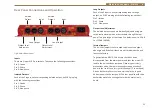
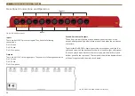
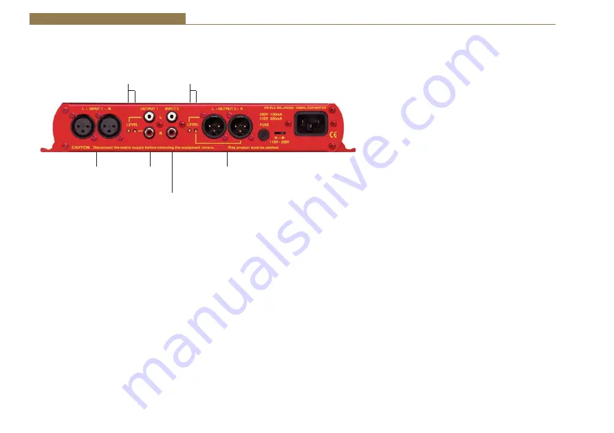
Fig 5-3: RB-BL2 Rear Panel
Balanced to Unbalanced Connections
Inputs 1 (Left & Right)
dŚĞy>ZϯƉŝŶƐŽĐŬĞƚƐƵƐĞĚĨŽƌƚŚĞůĞĨƚĂŶĚƌŝŐŚƚĐŚĂŶŶĞůƐŝŐŶĂůƐŽĨ/ŶƉƵƚϭ
ĂƌĞĞůĞĐƚƌŽŶŝĐĂůůLJďĂůĂŶĐĞĚĂŶĚŚĂǀĞĂŶŝŵƉĞĚĂŶĐĞŽĨϮϬŬɏďƌŝĚŐŝŶŐ͘dŚĞLJ
are routed to unbalanced RCA (phono) outputs with an output impedance
ŽĨфϱϬɏ͘ĂĐŚy>ZŚĂƐƚŚĞĨŽůůŽǁŝŶŐĐŽŶŶĞĐƚŝŽŶƐ͗
Pin 1: Screen.
Pin 2: Phase.
Pin 3: Non-phase.
Unbalanced Output
Level
Adjustment
Balanced Output
Level
Adjustment
Stereo Balanced
Inputs
RCA Phono
Outputs
RCA Phono Inputs
Stereo
Balanced
Outputs
RCA Phono Outputs 1 (Left & Right)
These RCA (phono) outputs are unbalanced and have an
ŽƵƚƉƵƚŝŵƉĞĚĂŶĐĞŽĨфϱϬɏ͘
Output Level Adjustment
The output gain can be individually adjusted for left and
right channels through pre-set potentiometers which
are accessible through the rear panel. The gain of the
balanced to unbalanced converter is variable within a
range of 0dBu to -28dBu ref -0dBu into the balanced
input.
Unbalanced to Balanced Connections
RCA Phono Inputs 2 (Left & Right)
The left and right RCA inputs 2 are unbalanced and have
ĂŶŝŵƉĞĚĂŶĐĞŽĨϭϬŬɏ͘
dŚĞLJĂƌĞƌŽƵƚĞĚƚŽƚŚĞďĂůĂŶĐĞĚy>ZϯƉŝŶŽƵƚƉƵƚƐϮ͘
Outputs 2 (Left & Right)
dŚĞy>ZϯƉŝŶŽƵƚƉƵƚƉůƵŐĐŽŶŶĞĐƚŽƌƐĂƌĞĞůĞĐƚƌŽŶŝĐĂůůLJ
ďĂůĂŶĐĞĚǁŝƚŚĂŶŽƵƚƉƵƚŝŵƉĞĚĂŶĐĞŽĨфϱϬɏ͘dŚĞLJŚĂǀĞ
the following connections:
Pin 1: Screen.
Pin 2: Phase.
Pin 3: Non-phase.


