SN8P2711A
8-Bit Micro-Controller
SONiX TECHNOLOGY CO., LTD
Page 106
Version 0.1
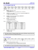
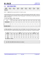
9.4 ADB
REGISTERS
0B2H
Bit 7
Bit 6
Bit 5
Bit 4
Bit 3
Bit 2
Bit 1
Bit 0
ADB
ADB15 ADB14 ADB13 ADB12 ADB11 ADB10 ADB9 ADB8
Read/Write
R R R R R R R R
After
reset
- - - - - - - -
Bit[7:0]
ADB[7:0]:
ADC high-byte data buffer of 12-bit ADC resolution.
ADB is ADC data buffer to store AD converter result. The ADB is only 8-bit register including bit 4~bit11 ADC data. To
combine ADB register and the low-nibble of ADR will get full 12-bit ADC data buffer. The ADC buffer is a read-only
register. In 8-bit ADC mode, the ADC data is stored in ADB register. In 12-bit ADC mode, the ADC data is stored in
ADB and ADR registers.
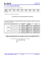
The AIN’s input voltage v.s. ADB’s output data
AIN n
ADB1
1
ADB10 ADB9 ADB8 ADB7 ADB6 ADB5 ADB4 ADB3 ADB2 ADB1 ADB0
0/4096*VREFH 0 0 0 0 0 0 0 0 0 0 0 0
1/4096*VREFH 0 0 0 0 0 0 0 0 0 0 0 1
.
. . . . . . . . . . . .
.
. . . . . . . . . . . .
.
. . . . . . . . . . . .
4094/4096*VREFH
1 1 1 1 1 1 1 1 1 1 1 0
4095/4096*VREFH
1 1 1 1 1 1 1 1 1 1 1 1
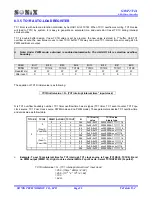
For different applications, users maybe need more than 8-bit resolution but less than 12-bit ADC converter. To process
the ADB and ADR data can make the job well. First, the AD resolution must be set 12-bit mode and then to execute
ADC converter routine. Then delete the LSB of ADC data and get the new resolution result. The table is as following.
ADB ADR
ADC
Resolution
ADB11 ADB10 ADB9 ADB8
ADB7
ADB6
ADB5
ADB4
ADB3 ADB2 ADB1
ADB0
8-bit
O O O O O O O O x x x x
9-bit
O O O O O O O O O x x x
10-bit
O O O O O O O O O O x x
11-bit
O O O O O O O O O O O x
12-bit
O O O O O O O O O O O O
O = Selected, x = Delete
Note: ADC buffer ADB initial value after reset is unknown.

