SN8P2711A
8-Bit Micro-Controller
SONiX TECHNOLOGY CO., LTD
Page 96
Version 0.1
8.3.6 TC1 CLOCK FREQUENCY OUTPUT (BUZZER)
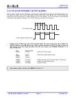
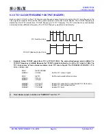
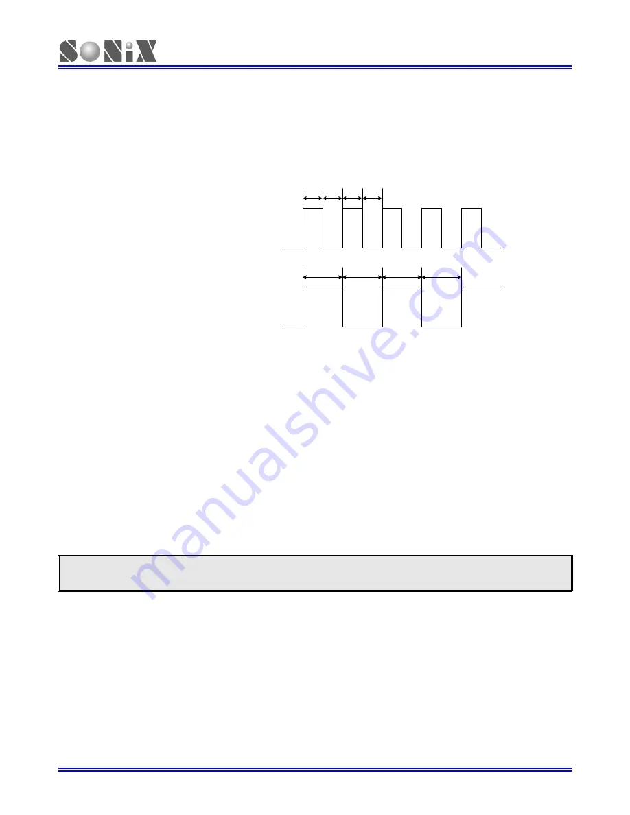
Buzzer output (TC1OUT) is from TC1 timer/counter frequency output function. By setting the TC1 clock frequency, the
clock signal is output to P5.3 and the P5.3 general purpose I/O function is auto-disable. The TC1OUT frequency is
divided by 2 from TC1 interval time. TC1OUT frequency is 1/2 TC1 frequency. The TC1 clock has many combinations
and easily to make difference frequency. The TC1OUT frequency waveform is as following.
1
2
3
4
1
2
3
4
TC1 Overflow Clock
TC1OUT (Buzzer) Output Clock
¾
Example: Setup TC1OUT output from TC1 to TC1OUT (P5.3). The external high-speed clock is 4MHz. The
TC1OUT frequency is 0.5KHz. Because the TC1OUT signal is divided by 2, set the TC1 clock to 1KHz. The
TC1 clock source is from external oscillator clock. TC1 rate is Fcpu/4. The TC1RATE2~TC1RATE1 = 110.
TC1C = TC1R = 131.
MOV
A,#01100000B
B0MOV
TC1M,A
; Set the TC1 rate to Fcpu/4
MOV
A,#131
; Set the auto-reload reference value
B0MOV
TC1C,A
B0MOV
TC1R,A
B0BSET
FTC1OUT
; Enable TC1 output to P5.3 and disable P5.3 I/O function
B0BSET
FALOAD1
; Enable TC1 auto-reload function
B0BSET
FTC1ENB
; Enable TC1 timer
Note: Buzzer output is enable, and “PWM1OUT” must be “0”.

