

3 | Product description
10 / 20
Operating instructions sonnenProtect 1300
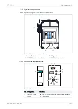
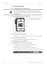
No. Designation
Function
2
‘ON” LED
Lights up when power supply is on (indicates emergency
operation).
3
‘AL’ LED
Lights up when an insulation fault occurs, i. e. when the insula-
tion resistance drops below the set alarm value (R
E
< R
AL
) (in
emergency operation).
4
Test key
Pressing the test key simulates an insulation fault, thereby
testing the function of the device. The ‘AL’ LED lights up and
the connection to the plug outlet of the sonnenProtect is in-
terrupted for as long as the test key is held.
5
Reset key
No function.
6
R
AL
setting
Turning sets the R
AL
alarm value (recommended setting:
100 kΩ/V).
Table 3: Description of the control and display elements
3.3 Type plate
The type plate is located on the outer surface of the sonnenProtect. The type plate
can be used to uniquely identify the sonnenProtect. The information on the type plate
is required for the safe use of the system and for service matters.
The following information is specified on the type plate:
• Item designation
• Item number
• Technical data
3.4 Symbols on the outside of the sonnenProtect
Symbol
Meaning
Warning: electrical voltage.
5 min
Warning: electrical voltage. Wait five minutes after switching off
(capacitor de-energising time).
CE mark. The product meets the requirements of the applicable
EU Directives.
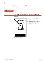
WEEE mark. The product must not be disposed of in household
waste, dispose of it through environmentally friendly collection
centres.


