;9G
Montagehinweise
Assembly instructions
Istruzioni di montaggio
Instructions de montage
Instrucciones de montaje
9
Instructions for installation and transport
The roof bracket mounting system is suitable for tiled roofs only. The installation may only be carried out by
qualified personnel. Only the supplied material should be used for the installation. Please inform yourself about
the applicable local norms and regulations before mounting and operating the solar system. Note: Installing a
collector array signifies an intervention into an existing roof. Roof coverings, e.g. tiles, shingle and slate, especially
in the case of converted and inhabited loft spaces or roofs with less than the minimum slope (with regards to the
covering), require additional on-site measures, e.g. sarking, as security against water penetration caused by wind
pressure and driving snow. This substructure and its connections to the main building structure should be
designed at the installation site in accordance with the local conditions. The roof structure must be able to take
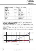
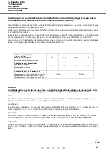
the wind and snow loads that can occur in the respective region. If snow loads are higher than 2.3kN/m² a metal
tile must be mounted beneath the roof bracket.
The use of a carrying strap is recommended for transporting the collector. The collector must not be lifted at the
connections or on the threading. Avoid impacts and mechanical action on the collector, especially on the solar
glass and the pipe connections. If the aluminium tray collectors have a protective coating, this must be protected
from sunlight and removed just before installation.
Structure
The collectors may only be mounted on sufficiently load-bearing roof surfaces and substructures. It is essential
that the structural load-bearing capacity of the roof and the substructure must be tested at the installation site
before mounting the collectors. Here, particular attention should be paid to the quality of the (timber) substructure
in terms of the stability of the screw joints necessary for installing the collectors. In particular, it is essential to
have the entire collector structure verified at the installation site according to DIN 1055, Part 4 & 5 or according
to country-specific regulations in regions with heavy snowfalls and strong winds (Note: 1m³ powder snow ~ 60kg
/ 1m³ wet snow ~ 200kg). The assessment should also take into account any special features of the particular
site that could lead to increased loads (foehn wind, air jets or eddy formations, etc). Collector arrays should always
be installed in such a way that any possible snow piles caused by snow trap grids (or the position of the collectors)
do not reach the collectors. There must be at least 1m distance from roof ridging or edges.
Lightning protection / Equipotential bonding of the building
In accordance with the lightning protection standard ÖVE/ÖNORM EN 62305 Part 1-4 the collector array cannot
be connected to the building's lightning protection. A safety distance of at least 1 m must be maintained from any
possible adjacent conducting object. For installations on metal substructures at the installation site, generally
qualified electricians must be consulted. To carry out a building potential equalisation, the metal tubes of the solar
circuit and all collector cases or fastenings must be connected to the main potential equalisation bus by a qualified
electrician in accordance with ÖVE/ÖNORM E 8001-1 or the country-specific standards.
Connections
(screw connections)
Depending on the design, the collectors must be connected with one another and/or the connection pipes using
screw fittings (1" internal/external thread) with flat-face sealing. Ensure correct placement of the flat gaskets. If
it is not intended to use flexible pipes as connecting elements, precautions must be taken to protect the connection
pipes against temperature fluctuations caused by heat expansion (expansion bends/flexible piping). In this case,
no more than 6 collectors may be connected in series. Larger collector arrays must be assembled with expansion
bends or flexible members inserted in the links (IMPORTANT: check the pump design). When tightening the
connections, always apply counter-pressure with a wrench or another spanner to prevent damage to the absorber.
Collector inclination / General notes
The collector is suitable for angles between 15° (minimum) and 75° (maximum).
Steps must be taken to ensure that water and other contaminants such as dust, etc. are prevented from getting
into the collector connections and ventilation holes.
Connecting support rails
If several support rails are mounted in series, these must be connected together with connectors above and below.
Warranty
Warranty claims can only be made if the supplier's own antifreeze is used and maintenance is carried out correctly.


