background image

4

3.

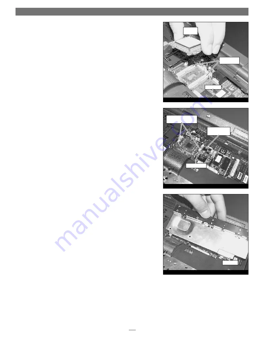
Carefully unseat the processor upgrade card by first lifting up the edge near-
est the keyboard, then lift up the edge nearest the screen. Once un-mated
from the logic board connectors, lift the processor card out toward the key-
board while holding the front edge higher than the screen edge 

(Figure 7)

.

Set the card aside near the stand-offs you just removed. 

Install the Crescendo/PB

1.

Remove the Crescendo card from the anti-static package, making sure to
handle the card by the edges. 

2.

Lower the card into the unit while holding it with the screen edge lower
than the keyboard edge. Align the screen end of the card connectors with
the logic board connectors. Once aligned, gently press on the outer edges of
the board (as indicated in 

Figure 8

) until the card’s connectors begin to

engage the main logic board connectors. Take care not to press on the board
component shown in 

Figure 8

. Then in one motion, lower the front edge of

the card and firmly press down until the card is seated. DO NOT FORCE IT!
The connection may be tight, but should not require excessive force during
insertion. If the card does not join properly with the logic board connectors,
carefully remove the card using the procedure above, check for bent pins,
and reinstall it using the procedure outlined above.

3.

Package the old processor card into the Crescendo’s anti-static package and
store it in a safe place.

4.

Reinstall the four stand-offs into their respective holes in the four corners of
the Crescendo card. The two long stand-offs run horizontal to the screen; the
two short stand-offs run horizontal to the keyboard. Reinstall the screen
cable shield if present.

Reinstall Metal Heat Shield

Reinstall the heat shield. Slide the front edge of the heat shield under the case,
then lower the back of the shield until it is flush with the logic board 

(Figure 9).

Reinstall the six screws. Make sure to put the two long screws at the rear corners
of the shield. 

Quick Start Guide for Crescendo/PB

Figure 8

Figure 9

Figure 7

processor

card

logic board

processor card

connectors

press here when seating

the Crescendo card

do NOT press on

this component

Crescendo/PB

heat shield

Summary of Contents for Crescendo PB G3

Page 1: ... Pacific Time Customer Service Phone 1 949 472 2772 E mail support sonnettech com Sonnet Technologies Inc 15 Whatney Irvine California 92618 2808 USA Tel 1 949 587 3500 Fax 1 949 457 6350 1999 Sonnet Technologies Inc Revised 2002 All rights reserved Sonnet the Sonnet logotype Simply Fast the Simply Fast logotype Encore and Crescendo are trademarks of Sonnet Technologies Inc Macintosh and Mac are t...

Page 2: ...ker grill located above the keyboard Remove the speaker grill by sliding it to the left and away from the computer Figure 1 You may need to use some gentle pressure to move it sideways if it has never been removed before Set the speaker grill aside 5 Place your finger or carefully slide the end of the Phillips screwdriver under the top edge of the keyboard and lift it up Rotate the keyboard forwar...

Page 3: ...ard 1 Locate the processor card Figure 6 It is in front of the keyboard cable connected to the logic board The processor card should also have four stand offs that secure it in place 2 If present remove the screen cable shield Use the hex head driver tool to loosen the stand offs Figure 6 Remove the stand offs and set them aside noting the two rear stand offs that run horizontal to the screen are ...

Page 4: ...card is seated DO NOT FORCE IT The connection may be tight but should not require excessive force during insertion If the card does not join properly with the logic board connectors carefully remove the card using the procedure above check for bent pins and reinstall it using the procedure outlined above 3 Package the old processor card into the Crescendo s anti static package and store it in a sa...

Page 5: ...at a new processor upgrade card is recognized at the next startup Clicking sounds from the speaker may be audible during this procedure This is normal and does not indicate a problem with the installation Turn On Computer 1 Before reinstalling the battery or any peripheral cables reconnect the A C power adapter and turn on your upgraded G3 PowerBook You should hear the startup tone and see the Cre...

Page 6: ... nor mal if clicking sounds from the speaker are audible during this procedure Repeat step 1 of the Turn On Computer section of the installation procedure No a The PowerBook power management circuit may need to be reset longer than the 30 seconds prescribed in the Reset Power Management section of the installation procedure Disconnect all peripherals and power sources battery and A C power adapter...

Reviews: