5
Chapter 3 – PCIe Card Installation and Chassis Setup Steps
10.
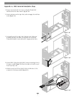
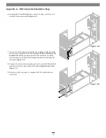
OPTIONAL STEP: If you are installing BNC connectors into the
chassis’ mounting holes, skip to the appendix at the end of this
document for instructions. Otherwise, go to the next step.
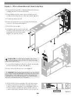
11.
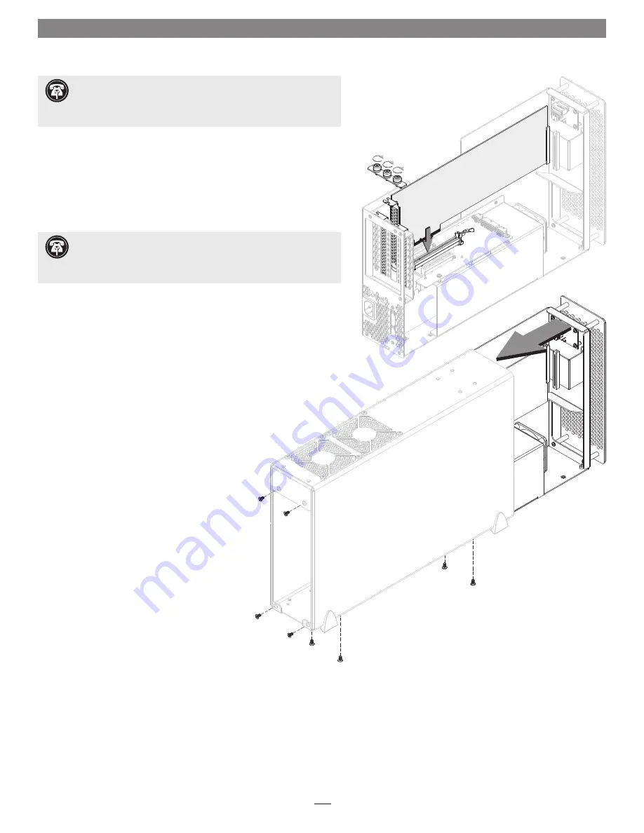
Remove a PCIe card from its packaging, handling the card by its edges
and without touching any components or gold connector pins.
12.
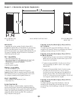
Line up the card’s connector with the slot, and then gently but firmly
press the card straight into the slot;
do not rock the card or force the
card into the slot
. If you encounter excessive resistance, check the
card’s connector and the slot for damage, and then try inserting the
card again
(Figure 4)
.
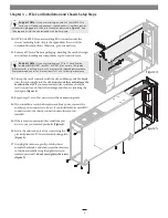
13.
Repeat steps 11 and 12 as necessary with any remaining cards.
14.
If you installed a card which requires auxiliary power, connect the
auxiliary power connector to it now. If you installed cables with BNC
connectors into the chassis, connect them to the card you
installed.
15.
If there are any unoccupied slots, install the port
access covers you removed previously
(Figure 4)
.
16.
Secure the cards and port access covers using the
previously-removed PCIe card bracket locking plate
(Figure 4)
.
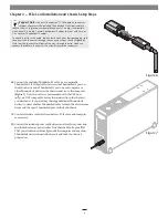
17.
Grasping the outer case, gently push the inner
assembly back inside, and then secure the outer case
to the inner assembly using the eight screws you
removed previously;
do not overtighten the screws
(Figure 5)
.
Figure 4
Figure 5
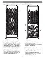
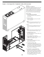
Support Note:
If you are installing an Avid Pro Tools|HDX PCIe
card, you will need to disconnect the Echo chassis‘ auxiliary power
wire harness plugged into the 6-pin connector indicated in
Figure 3
, and
then replace it with the one included with the Avid card.
Support Note:
If you are installing a x8 PCIe 1.1 card like the
original RED ROCKET (not RED ROCKET-X) or certain 10 Gigabit
Ethernet cards, installing it into slot 3 may result in reduced performance.
We recommend you install it into either slot 1 or 2 for best performance.