background image

3

Outer Case
Temperature-Controlled Fans 

These provide cooling for the installed PCIe cards and 
the chassis’ supporting Thunderbolt circuitry. They 
operate at a whisper when the cards are running cool, 
and automatically speed up in steps as the temperature 
rises. Do not block the fans or the vent holes on the 
front or back of the chassis to prevent overheating. 

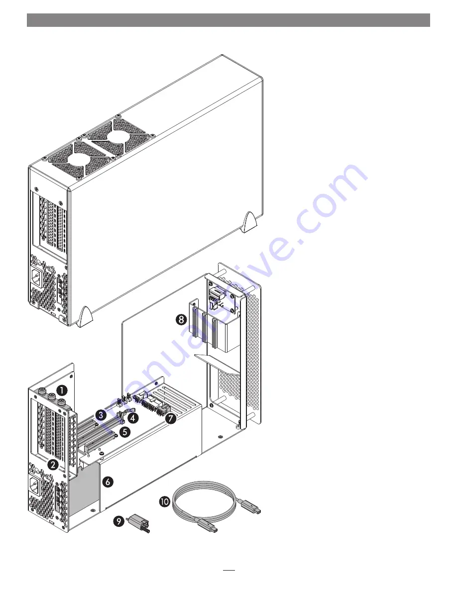
Inner Assembly
 1 –  PCIe Card Bracket Locking Plate 

This secures installed PCIe cards and port access 
covers in place.

 2 –  Port Access Covers 

These cover openings in the chassis when PCIe 
slots are unoccupied.

 3 –  Slot 1 

This is an x8 electrical (x8 mechanical) PCIe 2.0 slot. 
It is also compatible with PCIe 1.1 and 3.0 cards. 

 4 –  Slot 2 

This is an x8 electrical (x16 mechanical) PCIe 2.0 
slot. It is also compatible with PCIe 1.1 and 3.0 
cards. 

 5 –  Slot 3 

This is an x4 electrical (x8 mechanical) PCIe 2.0 slot. 
It is also compatible with PCIe 1.1 and 3.0 cards. 

 6 –  Thunderbolt Interface Card 

This card is installed in its own slot and may not be 
moved to another slot.

 7 –  6-Pin Auxilliary Power Connector 

Plugged into this connector is the auxiliary power 
cable for cards requiring extra power, such as the 
Avid Pro Tools|HDX or RED ROCKET-X.

 8 –  PCIe Card Guides 

When installing full-length cards, use these to 
support and secure the cards.

 9 –  Thunderbolt Connector Retainer Clip 

This secures a Thunderbolt connector plugged 
into the Echo chassis’ Thunderbolt port to prevent 
accidental cable disconnection. This clip is not 
compatible with optical Thunderbolt cables.

10–


Thunderbolt Cable 

Connect this cable between the Echo chassis and 
your computer (or other Thunderbolt device in the 
chain connected to the computer).

Chapter 2 – Echo Express III-D Description

Summary of Contents for Echo Express III-D

Page 1: ...ress III D Desktop Thunderbolt 2 to PCIe Card Expansion Chassis Quick Start Guide Video Available Online Visit http www sonnettech com product echoexpress3d html Click the Video Tab to View Installation Instructions For Windows ...

Page 2: ......

Page 3: ...on 7 Verify Echo Express III D is Recognized Verify Installed Cards are Recognized 5 Tips General Information and Known Issues 8 Tips General Information Known Issues 6 Specifications Precautions FCC Compliance and Support Information 9 Specifications Safety Precautions FCC Compliance Contacting Customer Service Visit Our Website A BNC Connector Installation Steps A Contents ...

Page 4: ...This page left intentionally blank ...

Page 5: ... card to reach the limit if not connected via Thunderbolt 2 Not all Mac compatible PCIe cards are also compatible with Windows 405 1 15 95 ECHO EXPRESS III D SIDE VIEW 258 5 10 18 97 1 3 82 ECHO EXPRESS III D FRONT VIEW ECHO EXPRESS III D REAR VIEW Introduction Congratulations on your purchase The Echo Express III D is a Thunderbolt 2 to PCI Express card expansion system through its PCIe slots you...

Page 6: ...e used for HD SDI output for the RED ROCKET X transcoding card or for MADI and word clock input and output from cards like RME s HDSPe MADI FX 3 Power Input Socket Connect the included AC power cable here 4 Thunderbolt Ports Connect a Thunderbolt cable between either port and your computer s Thunderbolt port or other Thunderbolt device in the chain connected to the computer the other may be used t...

Page 7: ...s also compatible with PCIe 1 1 and 3 0 cards 5 Slot 3 This is an x4 electrical x8 mechanical PCIe 2 0 slot It is also compatible with PCIe 1 1 and 3 0 cards 6 Thunderbolt Interface Card This card is installed in its own slot and may not be moved to another slot 7 6 Pin Auxilliary Power Connector Plugged into this connector is the auxiliary power cable for cards requiring extra power such as the A...

Page 8: ...it aside Figure 2 8 Remove and set aside the port access covers Figure 2 9 OPTIONAL STEP If you are installing a PCIe card which requires auxiliary power locate the wire harness connected to the 6 pin connector indicated in the graphic to the right Figure 3 Remove the cable twist tie securing the wire harness and move the loose connector aside for later connection Otherwise go to the next step Sup...

Page 9: ...stalled cables with BNC connectors into the chassis connect them to the card you installed 15 If there are any unoccupied slots install the port access covers you removed previously Figure 4 16 Secure the cards and port access covers using the previously removed PCIe card bracket locking plate Figure 4 17 Grasping the outer case gently push the inner assembly back inside and then secure the outer ...

Page 10: ...ween a wall outlet or power strip and the Echo chassis power socket Note that the power indicator on the Echo Express III D will not light until the computer and any other Thunderbolt device connected between it and the Echo chassis is powered on Figure 6 Support Note Sonnet s ThunderLok Thunderbolt connector retainer clip secures the included Thunderbolt cable to the Echo chassis to prevent accid...

Page 11: ...8 B Verify Installed Cards are Recognized 1 When a card is installed into one of Echo chassis PCIe slot s the PCIe slot listed as a port the Status should appear as connected 2 Click PCI Cards under the Hardware header in the left column Figure 9 3 At the top of the right column installed cards are listed By selecting a card at the top detailed information is listed You should see Yes next to Driv...

Page 12: ...press III D with the outer case removed and do not block any of the vents Otherwise the installed cards and Echo Express components may overheat Hot Plugging the Echo Express Expansion Chassis When certified Thunderbolt compatible cards used with Thunderbolt compatible drivers are installed in Echo Express III D you may connect and disconnect the chassis while the computer is on Of course if you h...

Page 13: ...nformation and online support files visit the Sonnet Web site at www sonnettech com support Register your product online at http registration sonnettech com to be informed of future upgrades and product releases Specifications External Connectors Two Thunderbolt 2 Power C14 type PCIe 2 0 Expansion Slots One x8 mechanical x8 electrical One x16 mechanical x8 electrical One x8 mechanical x4 electrica...

Page 14: ...ts edges rotate the bracket out of the inner assembly and then pull out the card Figure A 2 Set aside the Thunderbolt interface card on flat surface component side down 4 Insert the BNC cables through the BNC connector mounting holes in the inner assembly Figure A 3 Route the cables out over the top of the PCIe slot riser card 5 Slide the connector nuts over the BNC cables and then secure the conn...

Page 15: ... into the slot do not rock the card or force the card into the slot If you encounter excessive resistance check the card s connector and the slot for damage and then try inserting the card again Figure A 5 8 Using the two screws you removed previously secure the Thunderbolt interface card to the inner assembly do not overtighten the screws Figure A 5 9 Return to step 11 on page 5 to complete the P...

Page 16: ...eWire Mac the Mac logo and OS X are trademarks of Apple Inc registered in the United States and other countries Thunderbolt 2 and the Thunderbolt logo are trademarks of Intel Corporation in the U S and or other countries Other product names are trademarks of their respective owners Product specifications subject to change without notice Printed in the USA UG ECHO EXP3FD E E 102715 ...

Page 17: ......

Page 18: ......

Reviews: