

6
Chapter 3 – PCIe Card Installation and Chassis Setup Steps
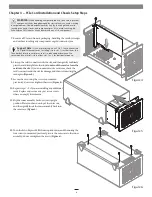
7.
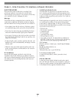
Remove a PCIe card from its packaging, handling the card by its edges
and without touching any components or gold connector pins.
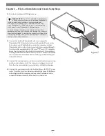
8.
Line up the card’s connector with the slot, and then gently but firmly
press the card straight into the slot;
do not rock the card or force the
card into the slot
. If you encounter excessive resistance, check the
card’s connector and the slot for damage, and then try inserting the
card again
(Figure 4)
.
9.
Secure the card using the screw you removed
previously; do not overtighten the screw
(Figure 4)
.
10.
Repeat steps 7 – 9 if you are installing any additional
cards. Replace and secure any port access covers
where an empty slot remains.
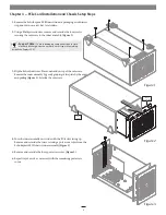
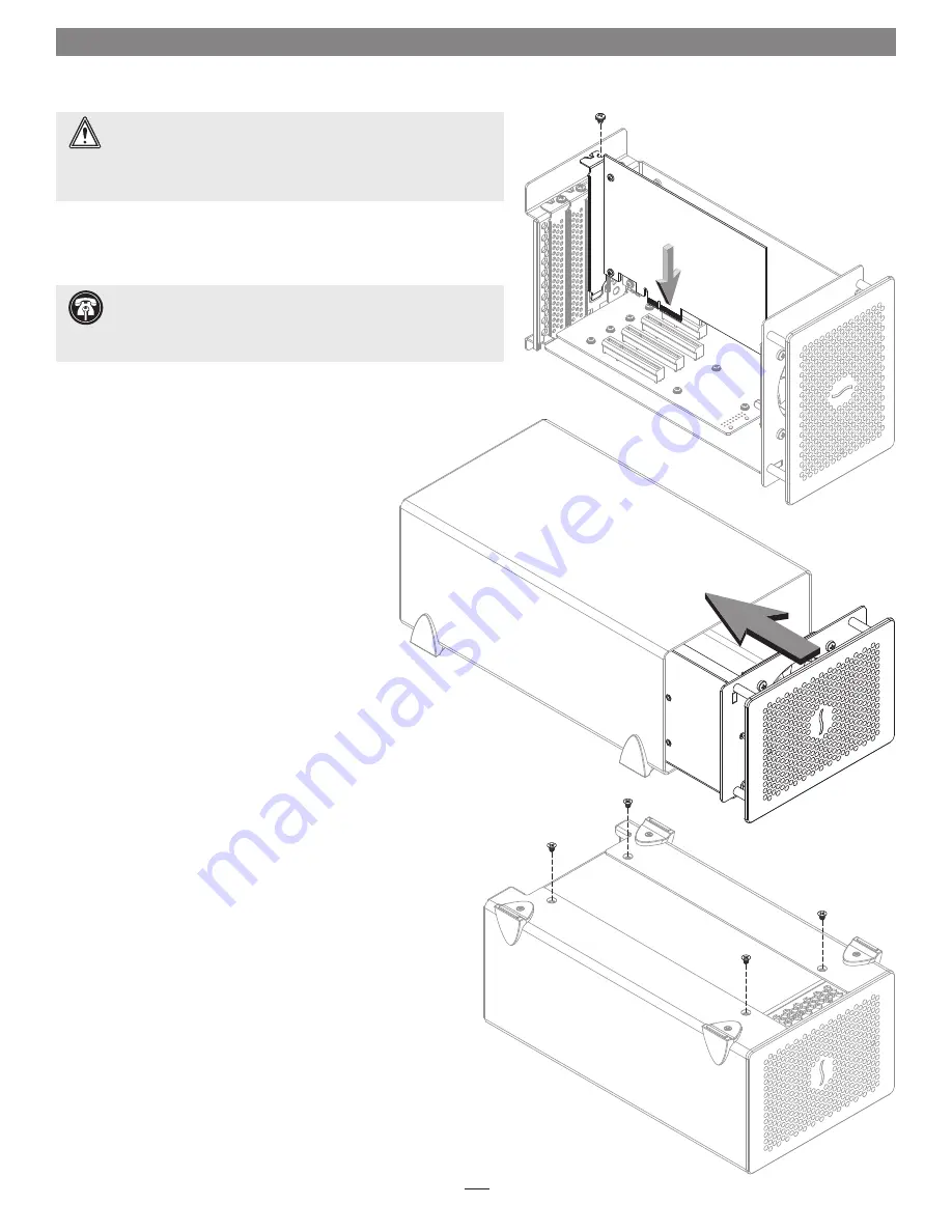
11.
Flip the inner assembly back over to its upright
position. Place your hand on top of the outer case,
and then gently insert the inner assembly back into
the outer case
(Figure 5)
.
12.
Turn the Echo Express SE III chassis upside-down, and then using the
four screws you removed previously, secure the outer case to the inner
assembly; do not overtighten the screws
(Figure 6)
.
WARNING:
When handling computer products, take care to prevent
components from being damaged by static electricity; avoid working
in carpeted areas. Handle expansion cards only by their edges and avoid
touching connector traces and component pins. Also, avoid touching the
Echo Express SE III chassis’ circuit boards and any of its components.
Figure 4
Figure 6
Figure 5
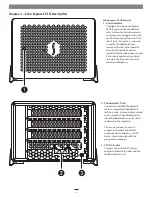
Support Note:
If you are installing an x8 PCIe 1.1 card like certain
10 Gigabit Ethernet cards, installing it into slot 1 (furthest from the
Thunderbolt interface card) may result in reduced performance. We
recommend you install it into either slot 1 or 2 for best performance.