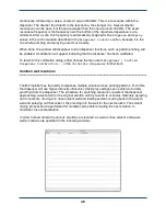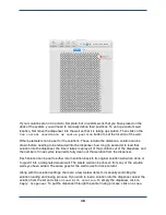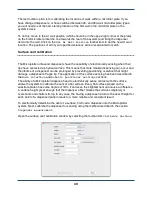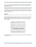
The feature width specified below the pattern dimensions is used to make the preview more
accurately reflect what will be printed, and does not control the actual dispensing size. It also is
used to set the spacing between lines when drawing a filled rectangle.
Each layer in the pattern or DXF file is listed below these options. Individual layers can be
enabled or disabled by using the checkbox next to their name. Only the enabled and visible
layers will be printed. These layers can be associated with solution wells that have been laid out
in SonoGuide by clicking next to them in the Solution Well column and choosing one of the
solution wells. This will associate that layer with that solution, and will cause the dispenser to be
loaded with that solution as needed before the layer is printed. See the
Solution Well
Locations
section of this chapter for how to set up solution well locations.
When you are ready to print, go to
File | Print
or use the keyboard shortcut
cmd + p
.
This will bring up the following window:
38
Summary of Contents for MICROPLOTTER II
Page 1: ...MICROPLOTTER II MANUAL REVISION 2 2 ...
Page 2: ...SONOPLOT INC 3030 LAURA LANE SUITE 120 MIDDLETON WI 53562 608 824 9311 CONTACT SONOPLOT COM 2 ...
Page 4: ...Dispenser refurbishing 59 Revision History 61 4 ...
Page 6: ......
Page 10: ......
Page 21: ...Fully installed Microplotter II system 19 ...
Page 22: ......
Page 58: ......
Page 62: ......
Page 64: ......
Page 66: ...60 ...


