C702
1221-7857 rev. 1
APPENDIX
A
P
P
E
NDIX
Audio output:
-
Earphone is the internal Earpiece speaker of the unit.
-
AUX earphone connected to the system connector.
-
Loudspeaker is the internal loudspeaker of the unit.
-
OFF is used to switch off the currently used Audio Loop.
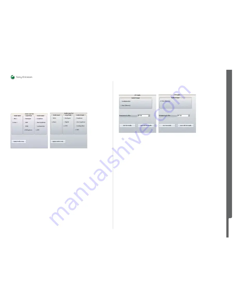
Examples of different Audio Loop Test setups in Fault Trace SW.
Picture
9
Picture
10
K800 Project Setup
K850 Project Setup
Note: Audio output and input pins can be used by disconnecting the blue SEPI connector from the
phone after the audio loop has been applied. Now the Portable Handsfree can be connected to the
System Connector. After function test operation, disconnect the PHF or external audio device from the
System Connector and connect the SEPI cable to proceed with other Audio Loop Tests.
FM Radio
-
To activate the FM radio, click at the Set FM Radio button.
-
To turn off the FM radio, click at the Turn OFF FM Radio button.
Audio output
Used for selecting Audio Output from the FM Radio. Most common Audio Outputs for all projects are
AUX Stereo (Portable Handsfree, PHF) or Loudspeaker.
Frequency in MHz
Frequency range box for the FM Radio. The frequency value can be selected in two different ways:
-
The first one is with up/down spin buttons
-
The second one is to type it directly into the Frequency field.
When typing directly into the Frequency field, the Frequency Span should be 100 KHz when changing
from one frequency to another. The Frequency Range used in the Troubleshooting Software is from
87.50 MHz to 108.00 MHz.
Examples of different FM Radio Test setups in the Troubleshooting Software
Picture 11
Picture 12
K850 Project FM Radio Setup K800 Project FM Radio Setup
Logic – Tab
Logic Functions
Note: Some of the Logic functions may not be possible to implement for all products due to limitations
in the ITP Software.
Note: There are some differences in the user interface depending on the phone project file loaded.
Some functions may not be available on all products.
Battery Calibration
Note: To perform this test only Power Supply channel 1 is needed. Make sure that the correct voltage
values are set for each test step, otherwise the test will fail.
The Battery Calibration test is similar to the Battery Calibration test performed in the factory
environment.
1.
Click 1. Battery Calibration.
2.
Click SET VBATT to 3.2 Volt.
3.
Adjust Power Supply channel 1 (the dummy battery) to 3.2 V.
4.
Click VBAT1.
5.
Click SET VBATT to 4.1 Volt.
6.
Adjust Power Supply channel 1 to 4.1 V and click VBAT2.
7.
Adjust Power Supply channel 1 to 3.8 V and click SET VBATT to 3.8 Volt.
8.
The test result (
Passed
or
Failed
) will now be displayed.
When the measured values are within the limits the calibration will be passed otherwise the test will be
failed. The compensation factor will be calculated and stored in the GDFS.
More information about the test limits can be found in the product specific Troubleshooting Manual and
in the Read Limits Table in the Battery and Current Calibration Test document.
Troubleshooting Software Documentation
SEMC Troubleshooting Manual
111
(115)
Summary of Contents for C702
Page 116: ...www s manuals com ...


