C702
1221-7857 rev. 1
TROUBLESHOOTING
TROU
B
L
E
S
H
O
OTIN
G
M
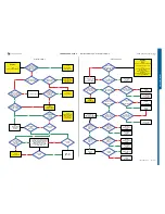
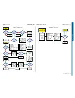
ain & VGA Camera - Camera Door Sensor & Flash LED Problems
START
Go to
Service Tests Menu and
perform:
Main and VGA Camera
Test
Are both
Main and VGA
Cameras having
problems
Load ITP SW into the phone
Use TRS Fixture
Connect:
Display, VBAT and DCIO/SEPI
Main and VGA Camera
must be mounted on the PBA !
Use Fault Trace SW
Perform Main and VGA Camera Test
Yes
Fault trace SW:
MMI, Misc, Init Screen Testing
Perform:
Main Camera Test and VGA Camera Test
Main and VGA
Camera working
properly
Flash the phone with
EMMA SUCR SW
Yes
No
Is the
Application
Result GPIO:
GPIO_03, GPIO_04 and
GPIO_05 = HIGH
Fault trace SW
1:
MMI, Misc, Init Screen Testing,
Activate
Main Camera Test
2:
Logic, GPIO Manager, Application, GPIO-Read:
GPIO_02, GPIO_03
GPIO_04, GPIO_05 and GPIO_09
SL 5 Replace
D2000
SL 4 Escalate
No
1.3 Volt DC
at MP 72 (TP2204
VCAM12)
Yes
SL 5 Replace
N2212
SL 4 Escalate
No
2.8 Volt DC at
MP 77 (TP2210
VCAMAF)
Yes
Replace
N2206
No
Yes
2.8V DC at
MP 71 (TP2207
VCAMSA) and 1.8V DC
at MP 52 (TP2208
VCAMIO)
Replace
N2209
No
13 MHz at
MP 76 (ST4304) and
1.8 Volt at
MP 74 (ST4303)
Yes
SL 5 Replace
D2000
SL 4 Escalate
No
Is the
Application
Result GPIO:
GPIO_02 = LOW and
GPIO_09 = HIGH
Yes
Fault trace SW
1:
MMI, Misc
Init Screen Testing
Activate:
VGA Camera Test
2:
Logic, GPIO Manager
Application
GPIO-Read:
GPIO_02 and GPIO_09
Yes
Is the
Application
Result GPIO:
GPIO_02 = HIGH and
GPIO_09 = LOW
Retest
Main and VGA
Camera
Yes
Is the
problem with
Main Camera
Replace
VGA Camera
SL 5 Replace
D2000
SL 4 Escalate
No
No
Replace
Main Camera
Yes
Main Camera
Ok
Claim
Main Camera
Yes
Replace
X4301
No
No
VGA Camera
Ok
Claim
VGA Camera
Yes
Replace
X4300
No
No
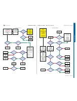
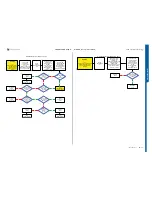
Main and VGA Camera Problems
START
Step 1:
Flash the phone with the EMMA SUCR SW
If successful claim SW Flash, if not go to Step 2.
Step 2:
Replace Flash FPC and retest the phone
If successful claim Flash FPC, if not go to Step 3.
Step 3:
Load ITP SW into the phone
Use Fault Trace SW
Use TRS Fixture
Connect: Flash FPC,
VBATT and DCIO/SEPI
and continue with the
Camera Door Sensor and Flash LED Problems TRS guide
3.8 Volt DC
at MP 87 (ST8101)
3.7 V - 3.8 V DC
at MP 88 (V8100
Anode)
No
SL 5 Replace
L8100
SL 4 Escalate
Yes
SL 5 Replace
V8100
SL 4 Escalate
Restart the Phone!
Fault trace SW
MMI
Misc
Init Screen Testing
Activate:
Camera Flash LED
Yes
1.5 V - 1.8 V DC
at MP 78 (R4231)
No
Replace
X4201
4.5 V – 5.0 V DC
at MP 87 (ST8101)
SL 5 Replace
N8100
SL 4 Escalate
No
Is
V8101
Short Circuit
Yes
SL 5 Replace
V8101
SL 4 Escalate
Yes
Replace
X4201
No
Is
Problem Solved
Claim Component
X4201
Yes
SL 5 Replace
D2000
SL 4 Escalate
No
Yes
No
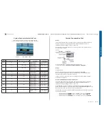
Camera Door Sensor and Flash LED Problems
SEMC Troubleshooting Manual
13
(115)
Summary of Contents for C702
Page 116: ...www s manuals com ...


