C702
1221-7857 rev. 1
TROUBLESHOOTING
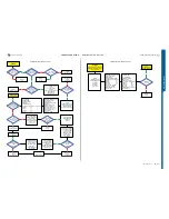
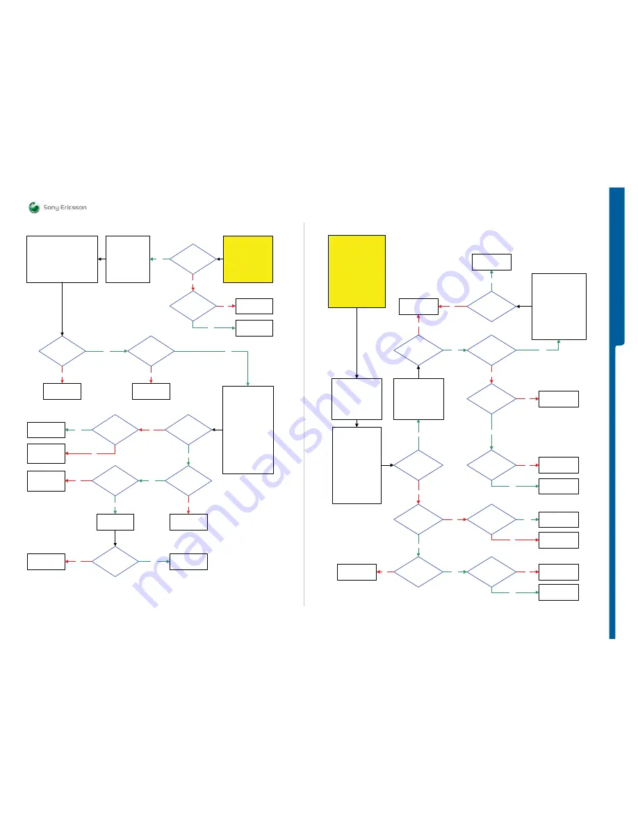
FM Radio Problem
TROU
B
L
E
S
H
O
OTIN
G
s - Bluetooth Problems
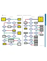
START
Perform System Connector
Protection Test
If test is pass
then continue with the
FM Radio Problems
TRS guide.
Fault trace SW
1:
Audio and FM Radio
FM Radio
Audio Output: Loudspeaker
Frequency: According to
Signal Generator Instrument Settings
Set FM Radio
2:
Logic, GPIO Manager, Application
GPIO-Read:
GPIO_00
Load ITP SW
into the phone.
Use TRS Fixture
Connect:
VBATT and DCIO/SEPI
Use Fault Trace SW
FM Radio
is not
working neither with
Loudspeaker nor
PHF set
No
Replace
N3101
PHF
working properly
during
Voice call
No
Yes
Yes
SL 5 Replace
N2000
SL 4 Escalate
Claim Component
System Connector
X2300
Is the
Application
GPIO_Read:
GPIO_00 = HIGH
SL 5 Replace
D2000
SL 4 Escalate
No
26 MHz BT_CLK
At MP 5 (R2101)
Yes
Replace
D2105
No
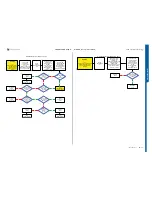
Disconnect:
DCIO/SEPI Cable
Connect:
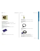
Customized FM Radio Cable
Black Lab Plug to
TRS Fixture GND Input and
PHF Connector to the
Phone System Connector
Signal Generator
Instrument Settings:
Frequency:
Use free Freq. Channel
Example:
103 MHz in Sweden
Amplitude: 25.0 uVrms
FM Dev:
+/-22.5 kHz
FM Rate:
1kHz
Yes
No
Replace
C3145 or C3146
Yes
SL 4 Replace
N1400
SL 5 Replace
L3301 and C3301
No
Can you
hear 1KHz Tone
out from the
Loudspeaker
Yes
SL 5 Replace
N2000
SL 4 Escalate
No
Yes
Is
L2408=Max 1.5 Ohm
L2410=Max 0.5 Ohm
SL 4 Replace
L2408
SL 5 Replace
L2410
No
Replace
System Connector
X2300
Yes
Signal Ok
More than
40mVolt AC Pk-PK
1 KHz signal at
MP 34 (C3145) and
MP 31 (C3146)
Yes
Is any of
C3145 or C3146
Short circuit
Replace
V2425
No
FM Radio Problems
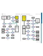
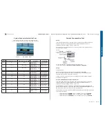
START
Step 1:
Flash the phone with EMMA
SUCR SW and retest the
phone.
If successful claim SW
Flashing
If not then go to Step 2.
Step 2:
Continue with the
Bluetooth Problems TRS
guide.
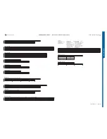
Fault trace SW
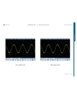
TX and RX
Bluetooth
Channel 0
Set MaxPwr MOD 0
Use
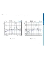
Spectrum Analyzer
Instrument settings:
Frequency: 2402 MHz
Span: 1MHz
Amplitude: -5dBm
BW: Auto
Use RF Probe with
10:1 Divider
Use Peak Search
Any Signal
at MP 54 (X1302
BT_ANT)
Fault Trace SW
TX and RX
Bluetooth
Channel 0
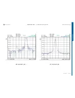
Set MaxPwr MOD 1
Use Spectrum Analyzer
with the previous
instrument settings
Is
MOD 1 Freq.
minimum 230 KHz
higher then
MOD 0 Freq.
No
Replace
N1400
Yes
-13dBm at
MP X1302
BT_ANT
(
±5dBm
)
Yes
Change the
Bluetooth channels
In Fault Trace SW
and test the output.
Use
Spectrum Analyzer
Span 10MHz
BW: Auto
Use RF Probe with
10:1 Divider
Use Peak Search when
changing the channel.
NOTE!
1MHz channel spacing
Yes
All channel
passed
Yes
No
-10dBm at
MP 65 (Z1400_Pin 1)
(Measure on the top of
Pin 1)
(
±5dBm
)
No
Replace
BT Antenna or
X1301 and X1302
Yes
-13dBm at
MP 63 (Z1400_Pin 5)
and
MP 64 (Z1400_Pin 7)
(
±5dBm
)
No
Replace
N1400
No
SL 5 Replace
Z1400
SL 4 Escalate
Yes
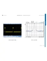
26 MHz Signal
At MP 5 (R2101
BT_CLK)
No
No
2.7 Volt DC at
MP 25 (ST2208
VBT27)
Yes
1.8 Volt DC
At MP 20 (ST2207
VDDE18) and 2.7 Volt DC
at MP 26 (ST2209
VDIG)
Yes
No
Replace
N1400
Yes
No
SL 5 Replace
N2000
SL 4 Escalate
SL 5 Replace
N2000
SL 4 Escalate
Load ITP SW
Into the phone
Use TRS Fixture
Connect:
VBATT and DCIO/SEPI
Use Fault Trace SW
Replace
BT Antenna or
X1301 and X1302
Replace
D2105
More
than 60 Kohm
between MP 5 (R2101)
(Red Probe)
and Shield Can Fence
(Black Probe)
Yes
Replace
N1400
No
Bluetooth Problems
SEMC Troubleshooting Manual
18
(115)
Summary of Contents for C702
Page 116: ...www s manuals com ...

