C702
1221-7857 rev. 1
TROUBLESHOOTING
Charging Test
TROU
B
L
E
S
H
O
OTIN
G
- ASIC Revision Test
Charging Test
To perform this test use:
-
Phone with the Normal SW (SSW)
-
Dummy Battery connected to Power Supply Channel 1 VBATT
Note! The resistance between GND and BDATA should be approximately 120 KOhm
-
Power Supply Channel 1 VBATT instrument settings:
Voltage: 3.0 to 4.2 Volts, according to VBATT row in the Reference Table.
Limiter: 2A
-
Power Supply Channel 2 DCIO/SEPI instrument settings:
Voltage: 5V
Limiter: 2A
Test instructions:
-
Disconnect the DCIO/SEPI Cable between each measurement and wait for phone to
shut down when changing VBATT voltage.
-
Take a note of Current measurements at Power Supply Channel 2 DCIO/SEPI and
Display charging indicator status, X seconds after DCIO/SEPI cable has been
inserted according to Test Time row in the reference table below.
-
Compare test results with reference table below, tol/-20%.
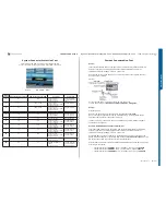
Reference Table
VBATT x Volt
3.0
3.1
3.2
3.3
3.4
3.5
3.6
3.7
3.8
3.9
4.0
4.1
4.2
Test Time x sec.
15s
15s
15s
30s
30s
30s
30s
30s
30s
30s
30s
30s
40s
DCIO/SEPI
Current mA
250
250
250
500
500
500
500
800-
1000
800-
1000
800-
1000
800-
1000
500-
750
0
Display indicate
charging
Nothing Nothing Nothing
Yes
Yes
Yes
Yes
Yes
Yes
Yes
Yes
Yes
Fully
Charged
Power Supply Channel 1 VBATT must allow reverse current.
If the charging current is Not equal to the reference table go to Charging problems TRS
Guide.
If the charging current is equal to the reference table then insert the normal battery and
test the charging current to verify that the phone battery is working properly.
Measure the voltage at the battery to check the current level.
If the battery is receiving the right current, then the phone and the battery are working
properly.
ASIC Revision Test
Note:
The Keypad Scan Test must be disabled in Fault Trace SW when performing this test.
The purpose of this test is to check the following items:
-
Verify that the ASIC is correctly mounted, the communication works and that
the revision is correct.
The tested ASICs are:
-
D2000 (Anja)
-
N2000 (Vera)
-
N1400 (Bluetooth and FM Radio ASIC)
-
N1200 (Thor)
-
N1430 (A-GPS Module)
To perform this test use:
-
Phone with ITP SW
-
TRS Fixture
-
Power Supply Channel 1 VBATT (Voltage: 3.8V, Limiter: 2A)
-
Power Supply Channel 2 DCIO/SEPI (Voltage: 5V, Limiter: 2A)
-
Fault Trace SW and go to: General – Asic Revisions – Read All
Reference return value table:
ASIC
Description
Part number
Return value (hex)
D2000
CPU (Anja)
1200-0186
0xC9
N2000
Power
Management
(Vera)
1000-8142 0xC7
Bluetooth
Firmware
Revision
Ox5,0x1
Chip ID
0x0,0x0,0x0,0x0
N1400
1200-6182
Will always return 0 on STLC because Chip ID is
not supported.
N1400
FM Radio
1200-6182
0x800
GSM Radio
Module (Thor)
Revision R1A:
0x7
Revision R1B:
0x8
N1200
1200-0158
N1430
A-GPS Module
1200-0700
254,0,253,192,0,242,113,9,16,252
SEMC Troubleshooting Manual
24
(115)
Summary of Contents for C702
Page 116: ...www s manuals com ...


