background image

4

SECTION 2

GENERAL DESCRIPTIONS
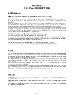
2.1 Multi-band :

CMD-Z7 support E-GSM 900 and GSM 1800 multi-band functionality.

For the use in Europe and in other countries worldwide, ETSI has specified GSM standards into two frequency
bands. That is the 900-MHz and 1800-MHz band and is usually referred to as GSM900 and GSM1800 (formerly
DCS1800).
While the 900-MHz band has 124 channels (extended version: 175), the 1800-MHz band with its 375 channels
provides a three-times higher capacity. Not only as a result of this large range of channels but also due to the low
transmission power and the transmission distance, GSM1800 supports a higher quantity of RF-channels.
The Dual band technology enables a network operator with spectrum at both 900MHz and 1800MHz to support the
seamless use of dual band handsets across both frequencies. By supporting seamless handovers between
900MHz and 1800MHz, Dual band networks can provide major benefits in terms of capacity enhancement and
revenue optimisation through the introduction of new services.

The CMD-Z7 is a phase II, GSM900 class 4, GSM1800 class 1 mobile phone.
The nominal maximum output power for GSM900 is 2W, for GSM1800 1W.
It supports the extra functionality required for multi-band mobile stations: Inter-band/”seamless” hand-over,
channel assignment, cell selection and re-selection, all between both bands within a Public Land Mobile Network.
The manual and automatic PLMN selection in both bands is given.

The user does not need any special action to use the multi-band functionality of the phone.
Users are able to manually roam between PLMN’s operating in E-GSM900 and GSM1800 bands.

E-GSM


With the further development of the GSM standard, an additional range of frequencies has been made available to
the “Global system for mobile communications”. For each of the two duplex frequency ranges, one for the forward
direction and one for the reverse direction, additional 10 MHz have been added to the bottom end of the bands,
extending the frequency range to 50 further channels.
The mobile station transmits in the 880- to 915 MHz range, and the base station transmits in the 925- to 960 MHz
range. A duplex spacing of 45 MHz is used, the base station always transmits on the high side of the duplex
frequency pair.
The numbering for these additional channels is from 974 to 1023. This is done to avoid assigning one channel
number twice within the same standard.
Compared to the primary GSM system, Channel number 0 is used in the extended GSM system, since it does not
make sense to reserve it at a guard band within the E-GSM bands. Now, the lowest channel, number 974 (880.0
MHz), serves as the guard band between GSM and other services on lower frequencies.

GSM 1800


GSM-1800 uses the frequency ranges of 1710 to 1785 MHz in the uplink direction, and 1805 to 1880 MHz in the
downlink direction.
From these figures it follows that the duplex spacing is 95 MHz with 374 channels with bandwidths of 200 kHz
each.
The channels are numbered from 512 to 885 in order to distinguish them from the channels in the primary and
extended GSM frequency bands.

Summary of Contents for CMD-Z7

Page 1: ...ion full graphics display 4 Grey scale type Resolution 96 x 92 pixels 7 lines excluding 1 status icon line proportional font Channel spacing 200 kHz Number of channels E GSM 900 174 GSM 1800 374 Frequency stability Transmit frequency drift synchronized 0 1 p p m Antenna type Patch antenna RF output power E GSM 900 2W 33dbm GSM 1800 1W 30dbm Battery Lithium Polymer 680 mAh Standby 50 220 h Network ...

Page 2: ...stor to a common ground point A quick release skin contact device with a flexible cord which has a built in safety resistor of a range between 5 2K Ω and 1 2MΩ shall be used The flexible cord must be attached to a dissipative earth point All containers and storage must be of the conductive type Batteries This device contains an internal battery in addition to the external battery pack These batter...

Page 3: ...ic Features 08 3 2 Security Codes 09 3 3 Icon Glossary 10 3 4 Menu Overview 10 3 5 Applications Menu 10 SECTION 4 Disassembling Testing 4 1 Disassembly 11 13 4 2 Interface to GSM Tester 14 4 3 Jigs and Tools 15 SECTION 5 Programming Instructions 5 1 Requirement 16 5 2 Hardware Set up 16 5 3 Software Set up 16 5 3 1 Software Download to Mobile 16 17 5 3 2 Save Personal Data in Mobile 17 5 3 3 Reset...

Page 4: ... given The user does not need any special action to use the multi band functionality of the phone Users are able to manually roam between PLMN s operating in E GSM900 and GSM1800 bands E GSM With the further development of the GSM standard an additional range of frequencies has been made available to the Global system for mobile communications For each of the two duplex frequency ranges one for th...

Page 5: ...tandards At first the Full Rate FR Codec was introduced With new requirements concerning speech quality and availability of radio channel resources two further standards were introduced the Half Rate HR Codec and the Enhanced Full Rate EFR Codec The Half Rate HR Codec requires only half the channel capacity of a Full Rate FR Channel The Enhanced Full Rate EFR Codec requires the same radio channel ...

Page 6: ... 6 Battery Safety The battery pack contains a single Li polymer cell a safety circuitry and in addition a microprocessor unit which manages RTC information by reading out the binary counter value in the microprocessor The charging circuitry and the safety circuitry together guarantee a double fail safe battery pack This means that each component can be either short or open and still all the safety...

Page 7: ...unctionality can be assigned on an accessory by accessory basis to be input output or interrupt Charge The Charge pin represents the positive contact for the charging funtionality GND The Ground pin represents the digital interface and charger return current ID This pin shows the presence of an accessory and is also an analog ID for the accessory Accessories which provide charger functionality onl...

Page 8: ...Press the Jog Dial straight Opens Menu in Standby Mode into the phone Selects an option highlighted in the display Keep the Jog Dial pressed Dials the phone number selected Press the Jog Dial forward Exits from one menu to the previous screen Also ends a call Press the Jog Dial backward Opens the pop up menu Also opens help 1 Ear piece 2 Advanced Jog Dial 3 Voice Mail Key 4 Keypad 5 Microphone 6 F...

Page 9: ...PIN 2 Personal Unblocking Key PUK PUK 2 8 Used to unblock PIN and PIN 2 A PIN or PIN 2 will become blocked if the wrong PIN or PIN 2 is entered three times When the blocked PIN or PIN 2 is unblocked a new PIN or PIN 2 must be entered If the wrong PUK or PUK 2 is entered 10 times the SIM card will be unusable Supplied by the Service Provider Bearing Password 4 Controls the call bar function If the ...

Page 10: ...gth SMS Envelope Icon Voicemail Alarm Silent Mode Vibra Alert Single Beep Outdoor Mode Ringer off Conversation Privacy ciphering not supportet T9 Text editing system Paste ICON Explanation Missed calls Incoming call barring Outgoing call barring Incoming Outgoing call barring Conditional Divert Unconditional Divert Active call Call hold Mute Microphone Headset connected active call Handsfree Kit c...

Page 11: ...icker and the number within the set memory allowed In case of replacing the lower cabinet it is to make sure that the IMEI Sticker mounted on the lower case visible from the battery compartment will be replaced to the new housing part as well Follow the disassembly procedure in the numerical order given CABINET UPPER LOWER MAIN BOARD ASS Y NOTE Do not detach the shield case from the main board ...

Page 12: ... ASS Y FRAME LCD ASS Y Note 1 Certain repairs may require that the 5 0 66 has to be detached from the 02 8 Note 2 On reassembly the 5 0 66 must be placed after the 02 8 and the 8 66 have been put back into the 8 6833257 ...

Page 13: ...13 GUIDE KEY SUPPORT ANTENNA CABINET LOWER Re assembly procedure To re assemble the unit apply the reverse order of the above mention disassembly procedure ...

Page 14: ...is unit acts as a base station providing all the necessary GSM signalling requirements and provides GSM signal measuring facilities as well CMD Z 7 Battery Pack Test SIM Card RF input Connector STC 05 Part No 3 235 700 01 RF output SMA jack Use special RF Adapter for connection of STC 05 to your GSM Tester ...

Page 15: ...For Connection To GSM Measure Equipment Level Test Procedure with GSM TESTER recommendation Simulate GSM call processing to check the functionality of transmitting and receiving audio signals of loudspeaker and microphone Basic GSM transmission reception parameter testing to ensure that handset s performance compiles with standard GSM specification DATA TRANSFER CABLE HOOK RELEASE JIG SERVICE TEST...

Page 16: ...ure the Flash Loader will attempt to perform data control operations which are not generally permitted by original SIMs The test SIM is not absolutely necessary for a generally software update although it is useful Attach battery pack to CMD Z7 the CMD Z7 is powered up from the battery pack The initial settings of the flash exe program may not correspond with the normally correct settings It is hi...

Page 17: ...ect a new mobile and click on Write Data or save it on the disc using File Save option When the message write user data complete appears disconnect the Data Transfer Cable and make sure that the attached battery pack will be removed do not switch off the terminal with the ON OFF key 5 3 3 Reset of User Data Erase Data Check if the settings for the Com Port and Speed are correct Switch on the CMD Z...

Page 18: ...1 211 725 7 51 3 046 953 01 5 1 66 1 816 067 11 211 725 3 1 3 046 952 01 5 1 66 5 1 754 193 11 17 11 3 7 60 3 235 142 01 86 21 5 1 A 3649 363 A 2 68 66 A 3649 361 A 5 0 66 1 796 133 11 2 6 7 3 237 037 02 6 9 1 544 848 11 08 7 725 1 804 381 11 02 8 1 756 187 11 77 5 3 X 3381 121 1 8 66 X 3381 193 1 1 7 2 5 66 3 235 131 01 3 A 3649 388 A 77 5 3 235 132 01 8 6833257 3 235 134 01 3 5 A 3622 547 A 0281...

Page 19: ...3 233 439 42 0 18 16758 7 21 87 3 233 439 52 0 18 16758 7 21 7 1 3 233 439 62 0 18 16758 7 21 63 1 6 3 233 439 72 0 18 16758 7 21 32578 8 6 3 233 440 12 0 18 16758 7 21 3 233 440 22 0 18 16758 7 21 32 6 3 233 440 32 0 18 16758 7 21 785 6 3 233 440 62 0 18 16758 7 21 6 6 Sony Ericsson Mobile Communications AB 9 870 405 01 2001 9 Published by After Sales Service 101 AC adapter 1 102 Lithium Polymer ...

Reviews: