C905
1222-9526 rev. 1
TROUBLESHOOTING
TROU
B
L
E
S
H
O
OTIN
G
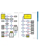
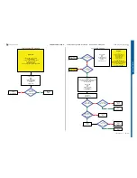
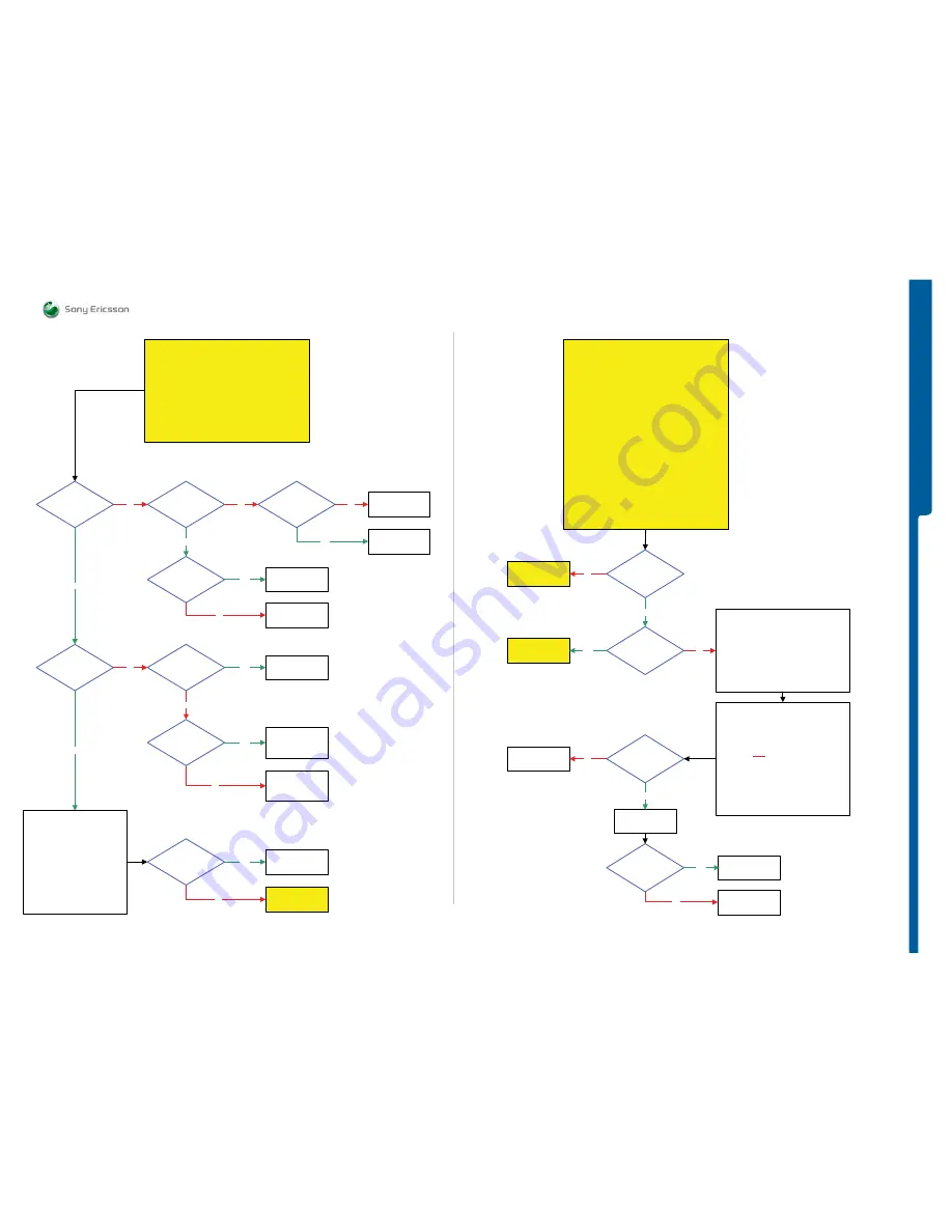
Dead Phone Problems - Display Problems
START
NOTE !
Before following this guide the
Dead Phone Problems part 2 TRS guide
must be finished
Is the
VCORE12
Voltage
Ok
1.1V – 1.2V DC
at MP 115
(V2201_Cathode)
3.8 Volt DC at
MP 114 (L2201)
No
Replace
L2201
No
Yes
No
Yes
Is
MP 116 (ST2209)
Short circuit to the
PBA GND (Shield
Can Fence)
Replace
L2200
No
SL 5 Replace
N2000 or N2010
SL 4 Escalate
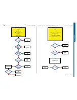
Is the
VCORE18/VMEM18
Voltage
Ok
No
No
1.8 Volt DC at
MP 40 (ST2225)
SL 4 Replace
N2200
SL 5 Replace
N2010
No
Yes
Yes
Yes
Is the
ITP SW Flash
Successful
SL 5 Replace
N2020
SL 4 Escalate
Yes
No
Yes
SL 5 Replace
V2201 or N2000
SL 4 Escalate
Is
MP 40 (ST2225)
Short circuit to the
PBA GND
(Shield
Can Fence)
SL 5 Replace
N2010
SL 4 Escalate
Yes
SL 4 Replace
N2200
SL 5 Replace
L2202
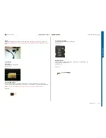
Step 1:
Disconnect:
VBATT and DCIO/SEPI
Step 2:
Connect:
Key Flex Assy and Slider FPC Assy
to the PBA
Connect: VBATT
Only
Step 3:
Use EMMA SW
Press the ”C” key and Connect
USB Cable from the PC to the PBA
Flash the Phone with ITP SW
Go to USB and
Software Flash
Problems TRS guide
Dead Phone Problems part 3
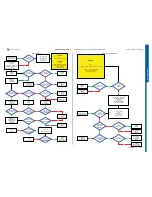
Is the
Display Backlights
Ok
Go to
Dispaly illumination
Problems TRS guide
No
Is the picture
too dark or
too light
Yes
Go to
Opto Sensor
Problems TRS guide
No
Disconnect: VBATT and DCIO/SEPI and
Remove PBA from the TRS Fixture
Use Digital Multimeter instrument (DMM)
and perform:
Z4200, Z4201 and Z4202
Display Filter Test 1 and 2
NOTE !
Be very careful when you're cutting the
Shield Can Fence to avoid component damage
Yes
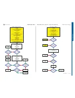
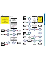
START
Step 1:
Flash the Phone with EMMA SUCR SW
If successful claim SW Flash
If not go to step 2.
Step 2:
Load ITP SW into the Phone
Use TRS Fixture
Connect:
PBA Key Flex Flip, Slider FPC Assy and Display
to the PBA
Connect: VBATT and DCIO/SEPI
Use Fault Trace SW and go to:
MMI
Misc
Init Screen Testing
Display Pattern
Activate:
TV Test Pattern
If Display is working on the TRS Fixture
then Replace
Display, PBA Key Flex Flip or Slider FPC Assy
If not then continue with
Display illumination Problems TRS guide
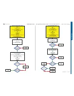
It is recommended to use microscope for these
measurements
Z4200, Z4201 and Z4202
Display Filter Test
Test 1:
Check if Pins: 1,2,3,4,5,6,7,8
are
NOT
short circuit to GND
Test 2:
Max 2 Ohm between the following pins:
Pin 1 and 5
Pin 2 and 6
Pin 3 and 7
Pin 4 and 8
NOTE !
Test 1 and 2 must be made on all filters
Are all
Display Filters
Ok
Replace
Z4200, Z4201 or
Z4202
No
Replace
X4200
Yes
Is the Display
Problem solved
Claim Component
X4200
Yes
SL 5 Replace
N2010
SL 4 Escalate
No
Display Problems
SEMC Troubleshooting Manual
10
(124)


