C905
1222-9526 rev. 1
APPENDIX
A
P
P
E
NDIX
Troubleshooting Fixture Setup Instructions
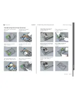
Connect SMK RF Probe to the X1500
RF Switch if needed, according to
picture 25.
Picture 25
Secure the SMK RF Probe with the RF
Probe locking device, according to
picture 26.
Picture 26
Connect the Customized FM Radio
Cable, according to Step 1 and 2.
Step 1:
Connect the Black Lab Plug to the TRS
Fixture GND input, according to
picture 27.
Picture 27
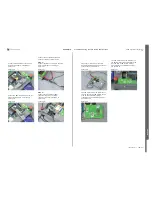
Step 2:
Connect the Hands-Free (PHF)
connector to he Phone system
connector (X2405), according to
picture 28.
Picture 28
Please see picture 29 for the final
Customized FM Radio Cable connection
setup with the TRS Fixture.
Picture 29
The PIN marked with the GND text on
the Top part of the TRS Fixture can be
used as MP TRS Fixture GND or
grounding for the oscilloscope probe,
see picture 30.
Picture 30
The PIN marked with the GND text on
the Bottom part of the TRS Fixture can
be used as MP TRS Fixture GND or
grounding for the oscilloscope probe,
see picture 31.
Picture 31
SEMC Troubleshooting Manual
124
(124)

