C905
1222-9526 rev. 1
TROUBLESHOOTING
TROU
B
L
E
S
H
O
OTIN
G
System Connector Protection Test - Current Consumption Test
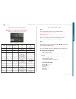
System Connector Protection Test
Perform Diode and Ohm measurements, use the DMM instrument.
Note!
T
he Battery must be removed from the Phone during this test.
Note! Connect the Black probe to X2405_PIN 9 (GND).
PIN_1
PIN_9 GND
PIN_12
System Conn.
X2405
(PIN Position)
Diode
Measurements
(Volt)
Ohm
Measurements
(Ohm)
SL 4
(Repair Action)
SL 5
(Repair Action)
1
0L
1M - 0L
X2405
L2407
N2421 if lower
C2439 if lower
2
0
0
X2405 if higher
L2406 if higher
No Action
3
2.6 – 2.8
12K
X2405 if higher
L2401 if higher
N3101 if lower or higher
C2443 if lower
4
0.7 - 1.2
1.0K – 1.1K
L2402 if higher
N3101 if lower or higher
X2405 if higher
C2442 if lower
5
1.8 – 2.0
2.0K – 2.2K
X2405 if higher
L2403 if higher
N3101 if lower or higher
C2448 if lower
6
1.8 – 2.0
2.0K – 2.2K
X2405 if higher
L2404 if higher
N3101 if lower or higher
C2447 if lower
7
0
75
X2405 if higher
V2414 if lower
R2443 if higher
N2700 if lower or higher
C2445 if lower
L2405 if higher
C2444 if lower
R2453 if higher
8
2.0 - 2.6
500K – 700K
X2405 if higher
R2448 if higher
V2417 if lower
N2422 if lower or higher
R2478 if higher
R2434 if higher
9
GND
GND
X2405 if higher
L2449 if higher
10
0.7 – 0L
50K – 0L
X2405
Z2400
V2415 if lower
N2420 if lower
R2445
11
0.7 – 0L
50K – 360K
X2405 if higher
Z2400 if higher
V2416 if lower
N2420 if lower or higher
R2446 if higher
12
0L
75K – 0L
V2412 if lower
V2202 if lower
C2440 if lower
C2441 if lower
Current Consumption Test
Step 1:
Insert a Local SIM Card and use the phone with the Normal SW (SSW).
Use Dummy Battery connected to Power Supply Channel 1 (VBATT).
Instrument settings: Voltage: 3.8 Volt, Limiter 3A.
Note: (Dummy Battery)
The resistance between GND and BDATA should be approximately 27KOhm.
Measure the current consumption when Phone is turned off.
Take a note of the current consumption at Power Supply Channel 1 (VBATT).
The Current consumption in off mode should be less than 1mA.
If more than 1mA go to Dead Phone Problems part 1 TRS guide.
Step 2:
Turn the Phone On:
Measure the deep sleep current max 6mA typical between 0-3mA. Make sure that the
operator is running with deep sleep mode.
Note: This operation can be switched off by operator if network is busy or heavily-loaded.
If phone using more than 6mA, then go to EMMA and run Software Update Contents
Refresh (SUCR SW).
Step 3 with Fault Trace SW application:
-
Flash the phone with ITP SW
-
Use Dummy Battery connected to the Power Supply Channel 1 (VBATT)
-
Use Fault Trace SW
Connect the:
-
Dummy Battery connected to the Power Supply Channel 1 (VBATT):
Instrument settings: Voltage: 3.8 Volt, Limiter 3 A
-
Connect DCIO/SEPI to the phone:
Instrument settings: Voltage: 5 Volt, Limiter 2 A
Perform the following tests:
-
Max TX Power GSM 850 MHz
Fault Trace SW settings:
TX and RX GSM
GSM Mode Settings:
TX Switched
GSM Radio Settings:
Select Band: GSM 850
Channel: 128
Power Level: 5
SEMC Troubleshooting Manual
31
(124)


