C905
1222-9526 rev. 1
TROUBLESHOOTING
Backup Capacitor Test
TROU
B
L
E
S
H
O
OTIN
G
- Charging Test
Backup Capacitor Test
To perform this test use:
-
Phone with ITP SW
-
Power Supply Channel 1 VBATT: Instrument settings: Voltage: 3.8V, Limiter: 2A
-
Power Supply Channel 2 DCIO/SEPI: Instrument settings Voltage: 5V, Limiter: 2A
This test should be performed in 3 steps:
Step1:
Measure the voltage at the Backup capacitor by using Fault Trace SW- Logic - ADC
Values – Read ADC Value (Reading 1).
Step2:
This step should be done 30 seconds after Step 1. Measure the voltage at the
Backup capacitor by using Fault Trace SW - Logic – ADC Values - ADC Channels
– Read ADC Value (Reading 2).
Step3:
Compare the difference between Reading 1 and Reading 2 with the reference table
below. If the Reading 1 value is between 50 and 680 go to Interval 1, if between 681
and 800 go to Interval 2, if between 801 and 880 go to Interval 3 and compare with
the Reading 2 – Reading 1 Min and Max Limits.
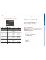
Reference Table:
Min
Max
Unit
Absolute readout
Reading 1
50
880
Dec
Reading 1 (Dec)
Reading 2 – Reading 1 (Dec)
Min Max
Interval 1 (50 – 680)
20
210
Interval 2 (681 – 800)
5
30
Interval 3 (801 – 880)
0
10
Note: The upper table contains the absolute limits for the readouts. The lower table
contains the allowed delta between the first and the second readout, separated in
time with 30 seconds.
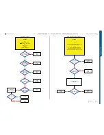
If the readings are out of limits replace C2214 Backup capacitor.
If the problem is not solved then SL 5 Replace N2000 SL 4 Escalate.
Charging Test
To perform this test use:
-
Phone with the Normal SW (SSW)
-
Dummy Battery connected to Power Supply Channel 1 (VBATT)
Note! The Dummy Battery should have approximately 27 KOhm resistance
between GND and BDATA.
-
Power Supply Channel 1 (VBATT)
Instrument settings:
Voltage: from 3.0 Volt to 4.2 Volt, according to VBATT row in the Reference Table.
Limiter: 2A
-
Power Supply Channel 2 (DCIO/SEPI)
Instrument settings:
Voltage: 5V
Limiter: 2A
Test instructions:
-
Disconnect the DCIO/SEPI Cable between each measurement and wait for the
phone to shut down when changing VBATT voltage.
-
Take a note of Current measurements at Power Supply Channel 2 DCIO/SEPI and
Display charging indicator X seconds after DCIO/SEPI cable has been inserted
according to Test Time row in the reference table below.
-
Compare test results with reference table below, tol/-20%.
Reference Table
VBATT x Volt
3.0
3.1
3.2
3.3
3.4
3.5
3.6
3.7
3.8
3.9
4.0
4.1
4.2
Test Time x sec.
15s
15s
15s
25s
25s
25s
25s
30s
30s
30s
30s
30s
45s
DCIO/SEPI
Current mA
250
250
250-
500
500
500
500
500
800-
1000
800-
1000
800-
1000
800-
1000
500-
750
0
Display indicate
charging
Nothing Nothing
Yes or
Nothing
Yes
Yes
Yes
Yes
Yes
Yes
Yes
Yes
Yes
Fully
Charged
Note! The Power Supply Channel 1 (VBATT) must allow reverse current.
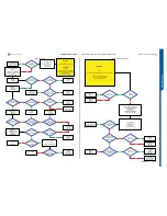
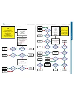
If the charging current is
NOT
equal to the reference table then go to:
Charging Problems TRS Guide.
If the charging current is equal to the reference table value then insert the normal battery
and test the charging current to verify that the phone battery is working properly.
Measure the voltage at the battery to define the current level.
If the battery is receiving the right current, then the phone and the battery are working
properly.
SEMC Troubleshooting Manual
33
(124)


