C905
1222-9526 rev. 1
FUNCTIONAL OVERVIEW
FU
N
C
T
IO
N
A
L O
V
E
R
V
IE
W
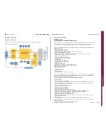
Technical Description
Charger Control
A programmable charger is used for battery charging. Limits can be set for the output
voltage at CHSENSE- and the output current from DCIO through the sense resistor to
CHSENSE-. The programmable charger is enabled or disabled by the assertion/negation
of the external signal DCIO. Parts of the programmable charger are activated and
deactivated depending on the level of VBAT. The rest of the programmable charger is
activated and deactivated through I2C.
The programmable charger supports the following functions:
• Constant current charging
• Constant voltage charging
• Trickle charging
• PWM controlled charging
• Over-voltage and over current detection
• Watchdog termination
• DCIO assertion/removal detection
• Voltage and current measure functions
• Low resistive path (reverse mode)
The programmable charger is able to control the voltage and limit the current to a load
seen at CHSENSE-. The programmable charger can also be run in PWM mode to turn the
charging on and off in accordance with the particular period and duty cycle. When the
charging is on, it is set to the current and voltage selected by I2C.
A low resistive path from VBAT to DCIO can be formed when DCIO is not detected.
When this setting is done in the appropriate registers, a lowering of CHREG to 0 V turns
on the external pass device. The pass device is automatically turned off when an
external source is detected on DCIO, or when the watchdog termination block times out.
The watchdog termination block must be active when the external switch is enabled,
both in normal
charging mode and in the low resistive path mode. The watchdog is set through the
serial interface, and if it has not been set again before timeout, the watchdog turns off
the external switch. The watchdog is disregarded during trickle charging. When no
battery is present, the system can be booted and supplied from DCIO by
applying the correct voltage on DCIO.
USB Charger
The analog baseband controller contains a standalone USB charger.
The USB charger has a separate input and incorporates full functionality during low VBAT.
The programmable charger supports the following functions:
• Trickle charging
• Constant current charging
• Watchdog termination
• Trickle LED indication
• VBUS assertion/removal detection
Resistance Identification and Temperature Measurement
The resistance identification mode utilizes the constant current source to feed the
battery data output while monitoring the voltage at the battery data node with general
purpose ADC the conversion is started through I2C.
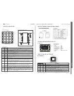
Resistance Identification (A) and Temperature Measurement (B):
SIM Interface
The SIM interface supplies level is shifting between the digital baseband controller and
the SIM/USIM card. Moreover, hard-wired SIM deactivation functionality manages
removal of a SIM card that has not been powered down.
Block Diagram of the SIM Interface:
SEMC Troubleshooting Manual
90
(124)


