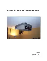
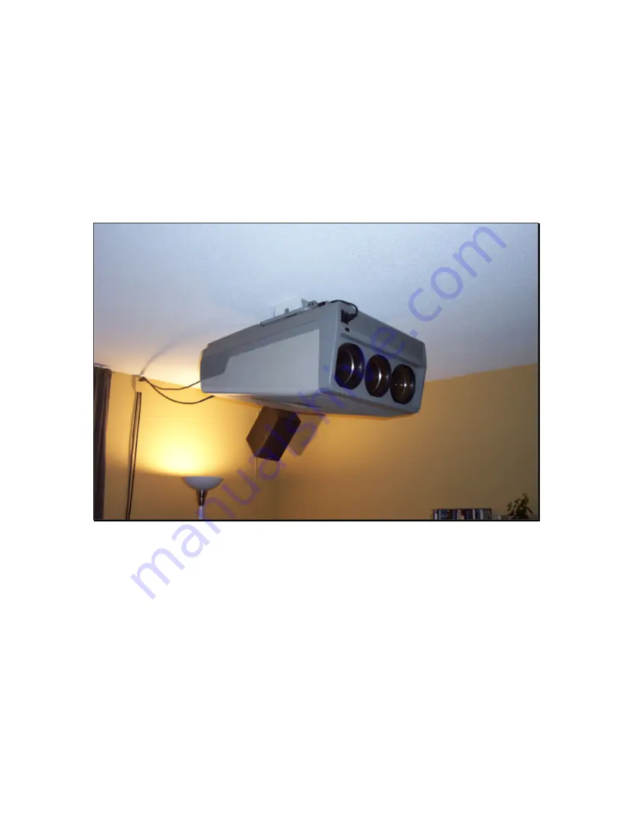
background image


Sony 1270Q Setup and Operation Manual 


Wes Hill 


February, 2002 

Summary of Contents for 1270Q CRT

Page 1: ...Sony 1270Q Setup and Operation Manual Wes Hill February 2002 ...

Page 2: ...ector Setup 2 1 Mechanical Setup 2 1 1 Throw Distance 2 1 2 Mount Setup 2 1 3 CRT Mechanical Setup 2 2 Electrical Setup 2 2 1 2 4 Pole Adjustment 2 3 Focus by Wes Hill 2 4 Convergence 2 4 1 Convergence for all Inputs 2 4 2 Individual Convergence Settings 2 5 Setting the G2 Adjustments 3 The Sony 12xx FAQ that separate doc 3 1 Focus by Guy Kuo 3 2 Cleaning Lenses 3 3 DIY Screen ...

Page 3: ...s the electron beam focus The electron beam is focused by 2 sets of magnets a 2 pole set and 4 pole set This isn t the most accurate way to control the electron beam higher end projectors use a combination of magnets and Electromagnetic beam focusing which allows for a much smaller beam allowing for much higher resolutions This is the reason that some PJ s with the same Sony 07MP tubes that the 12...

Page 4: ...nes if I am less than about 6 feet away from the screen and the picture is very sharp I have run at 540P 600P 666P 720P and 768P with 666P being the highest resolution I can make it resolve There has been some discussion on the AVS Forum which gives a mathematical solution to this exact topic with the verdict being about 600 to 700 scan lines being the maximum in 16 9 mode This depends on a lot of...

Page 5: ...ht to dark very quickly and hence the appearance of flicker Movie theatres also 48 Hz I believe are different than this as they are passing light through a translucent media and therefore doesn t appear to flicker very badly A CRT projector well Sony 12xx anyway seems to be somewhere in the middle as 48 Hz refresh does not flicker with the exception of a bright static windows desktop We all know t...

Page 6: ... you can see my screen PJ is on the low end of the brightness spectrum so to speak I would really like to go to a 54 x 96 screen with a 1 5 gain screen material I ve been looking at screen materials and have seen absolutely no hot spotting and a very wide field of view with a Stewart 1 5 gain This will be my screen of choice with my new projector which will be a 9 with at least an output of 275 AN...

Page 7: ... and sharpness This results in a throw distance of approximately 109 from the screen to the green tube I ve moved my projector closer to the screen to use more of the phosphor area This gives a brighter image and allows for a larger number of scan lines to be resolved The following is the method I used to maximize my phosphor use Set the projector on a table Center the image on the green see later...

Page 8: ... vertical Next you need to ensure the green tube is projecting and image perpendicular to the screen The way I do this is to measure from the wall to the center hole in the bottom of the projector Next I mark the front and rear of the projector along the center line I ensure that both of these marks are the same distance from the side wall I also mark this same distance on the screen or screen wal...

Page 9: ...RT face on the tape Now project the cross hair pattern and center it to these marks you may have to use the zone control as it gives a greater range of adjustment Turn the brightness and contrast down so you don t go blind in the process Save this as data for all inputs hold the MEMORY key down for about 10 seconds Remove the tape from the CRT faces clean the faces and re install the lenses Now br...

Page 10: ...sible This is where things start to get difficult Skip ahead to the focus section for more info on this 2 2 Electrical Adjustments 2 2 1 2 4 Pole Adjustment The magnet adjustments are done by moving the plastic tabs on the following picture If they ve never been adjusted before there will be white paint holding them from moving Grab a razor blade and cut the paint Very Important Note there is leth...

Page 11: ...sshair pattern cut off the CRT s that you aren t adjusting rotate the focus slightly counter clock wise from perfect focus adjust the 2 pole magnet rear so that the luminance point lies in the center of the flare The 4 Pole Magnet adjustment Output the dot pattern Rotate the focus to just clockwise of perfect focus Adjust the 4 pole magnet front magnet so the dot becomes round ...

Page 12: ...I use isn t any kind of standard it s just what I use for myself 5 CRT Spacer Sets CRT angle relative to screen size CRT Angle Lens Angle Allows for focusing acros the entire screen This angle is adjustable on both axis Lens Assembly Projector Chassis Lens Space To achieve the proper focal length for a given throw distance To get the mechanical focus perfect there are a few things that need to be ...

Page 13: ... for the timid so please be prepared to open a very large can of worms if you start this I really can t stress this enough The problem with the factory system is that it is designed for a range of screen sizes If you want perfect focus as most of us do this is unacceptable The thin plastic spacers blue arrow are designed put the CRT face at certain distance from the lens to provide the proper foca...

Page 14: ...ere are inherent problems to this design though you must make sure you don t adjust 1 corner too much or the lens case tabs can be strained or even broken Also the spacers must be removed as they are now useless Further more you must adjust the large spacers green arrows in concert with the goggle flappers in order to keep the image centered This is no easy task and will take many hours It has for...

Page 15: ...n the spacer you removed This will ensure that the proper amount of adjustment is possible Material List 12 M5 x 25 mm allen head bolts 12 5 mm Lock Nuts nuts 1 Very long 5 mm allen key some ingenuity will be needed here you likely wont find a 11 long allen key at Home Depot Installation 1 Measure the spacer between the lens base and the lens case tab red arrow below Lens Space in drawing above ...

Page 16: ...each in until you are approximately the distance you measured before spacer thickness It s likely easiest to go ahead and fire up the PJ and focus the green tube now Prior to adjusting the lens flapping I place the front most lens adjustment in the neutral position and focus the center of the screen Then I begin moving the lens slightly in one direction and refocus noting how the focus has reacted...

Page 17: ...cross the entire screen The resulting picture will amaze you Here s a picture of the completed install 2 4 Convergence There are at least 2 convergences you must do when setting up your PJ The first applies to all inputs and must be done when there is no input attached to the PJ The second is for a particular input bandwidth The memory structure of the Sony PJ s is such that it automatically saves...

Page 18: ...ime you mess with electronic focus or astig you ll need a total re convergence Don t worry it gets easier Even though sometimes it feels like you ve taken 1 step forward and 2 steps back sooner or later you ll see the light at the end of the tunnel Really you will 2 4 1 Initial Convergence Make sure you have no input attached to the PJ Press and hold the test key until the PJ asks if you want to e...

Page 19: ...same time You ll likely want to bump the BOW and SKEW adjustments feel free all of these adjustments can be done in any order Keep in mind that these settings are for the horizontal and vertical lines of the crosshairs only so only display this test pattern Hit the TEST key and display the cross hatch pattern Now you can move onto the PIN and KEY adjustments Have fun by now your eyes are probably ...

Page 20: ...inish up with zone convergence Do the blue and you re done for now Press and hold the MEMORY key until the PJ asks if you want to save this data for all memories hit the up arrow to agree 2 4 2 Individual Input Convergence Now with the proper input selected and being displayed go into the MAN mode and repeat the above adjustments until the convergence is perfect I seem to find that I have about 3 ...

Page 21: ...OTE This is slightly different on other 12xx series PJ s 1 Set brightness and contrast Brightness 50 Contrast 80 2 Disable the AKB Auto Cathode Bias On the CF2 board there is a connector with only 2 pins Short these pins 3 Call up the pluge pattern 5 IRE 0 IRE and 5 IRE 4 Set the Bias and Gain to factory defaults if possible Press the right and left arrow at the same time Else set Bias to 140 and ...

Reviews: