13
Chapter 6 - Q-Box & PD-Board Removal
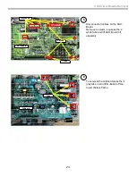
Access & Removal of Q-Box & PD-Board
(Digital Module Block DMB )
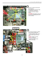
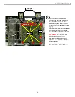
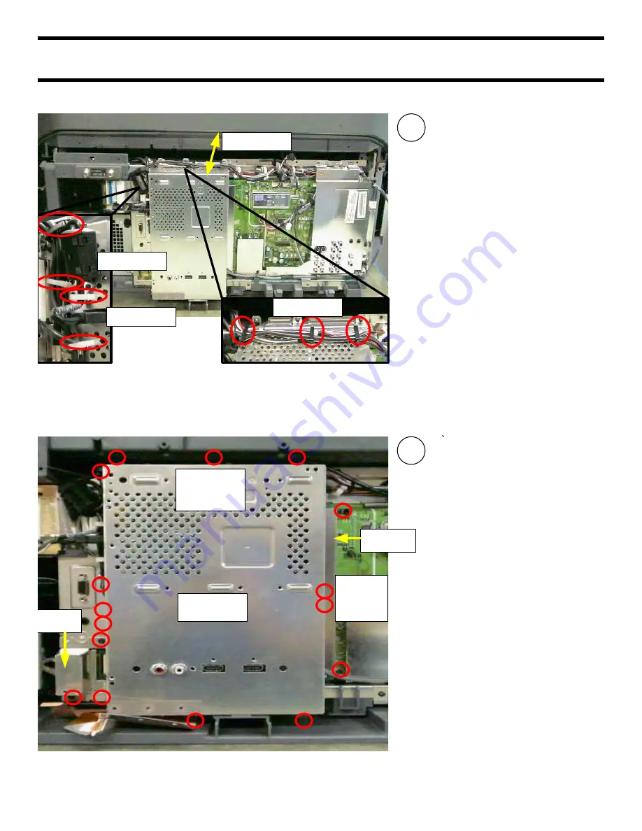
1
The Chassis only needs to be
slightly slid out to access the
screws and wire holders to
access the Q-Box and PD-
board.
Reference the “Complete PCB
Chassis” section for details to
free and slide out the chassis.
Remove all wires from wire
holders.
Disconnect USB cable
Slide Out
Wire Holders
Wire Holders
USB Cable
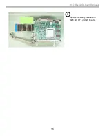
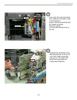
2
Remove 16 screws, Small
Cover, and the Connector
Cover to remove DMB outer
shield.
When all screws are removed,
pull the left-side of the shield
out first to clear the i -link
connectors on the right-side of
the shield.
Once i-link connectors are clear
pull shield straight off.
DMB Outer
Shield
Connector
Cover
Small
Cover
I-Link
Jack
Screws
(on side)
Screws
indicated by
red circles
Summary of Contents for 2005 SXRD KDS-R50XBR1
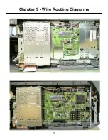
Page 26: ...24 Chapter 9 Wire Routing Diagrams Wire Routing Diagrams ...
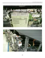
Page 27: ...25 9 Wire Routing Diagrams Wire Routing Diagrams cont ...
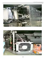
Page 28: ...26 9 Wire Routing Diagrams Wire Routing Diagrams cont ...
Page 29: ...27 9 Wire Routing Diagrams Wire Routing Diagrams cont ...
Page 30: ...28 9 Wire Routing Diagrams Wire Routing Diagrams cont ...


