3
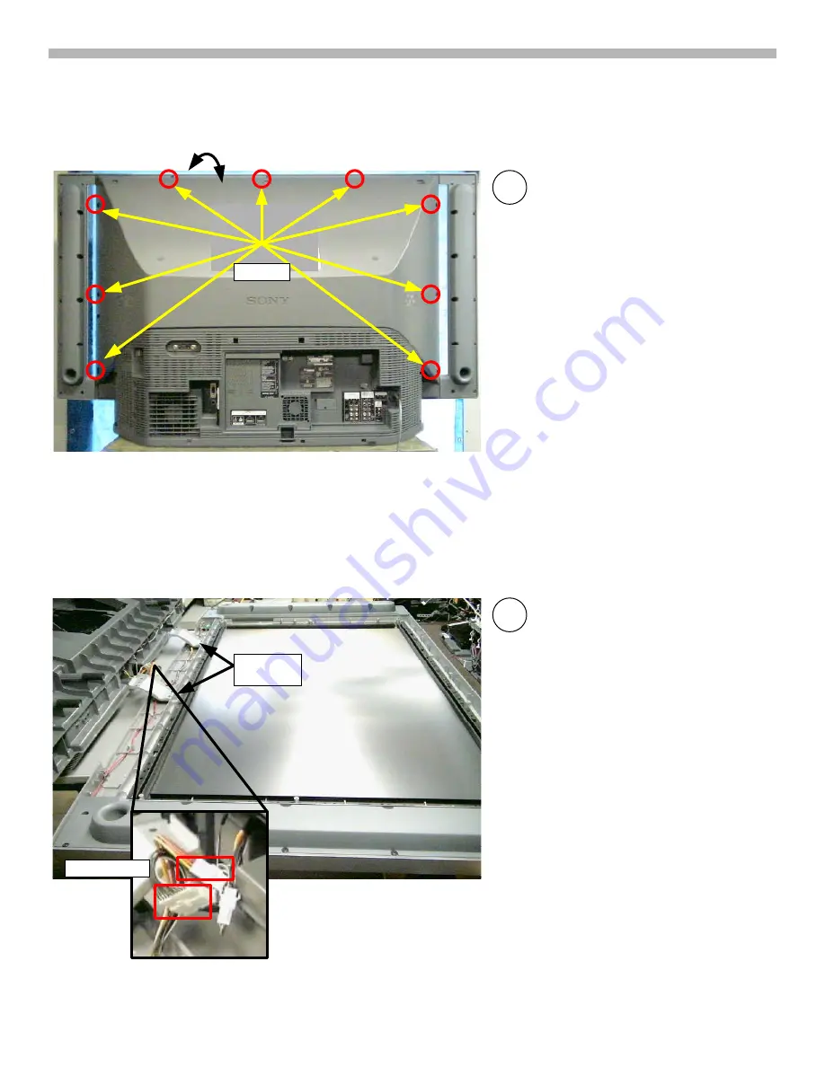
1. Screen Frame Removal
Screws
Leave top -center
screw for last
3
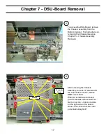
Remove 9 screws to release front
Screen Frame assembly.
CAUTION:
Leave the top-center
screw in place while removing the
eight other screws. Go around to the
front of the unit . Hold the screen
frame assembly and the rear mirror
assembly together at the top while
removing the last top-center screw.
Pull the Screen Frame assembly off
and lay down on a soft pad.
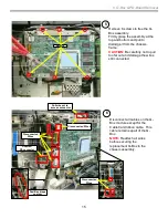
Screen Frame Removal (cont.)
4
Disconnect 2 connectors
CAUTION:
Do not stand the Screen
Frame assembly on the metal
brackets.
Connectors
Hold
Together
Metal
Brackets
Summary of Contents for 2005 SXRD KDS-R50XBR1
Page 26: ...24 Chapter 9 Wire Routing Diagrams Wire Routing Diagrams ...
Page 27: ...25 9 Wire Routing Diagrams Wire Routing Diagrams cont ...
Page 28: ...26 9 Wire Routing Diagrams Wire Routing Diagrams cont ...
Page 29: ...27 9 Wire Routing Diagrams Wire Routing Diagrams cont ...
Page 30: ...28 9 Wire Routing Diagrams Wire Routing Diagrams cont ...


