


1-13
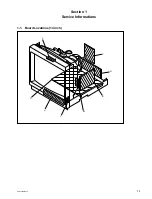
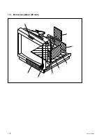
PVM-14L2/20L2
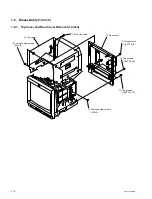
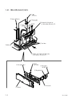
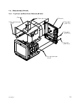
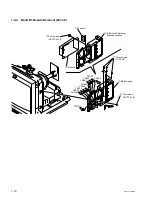
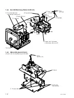
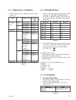
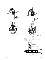
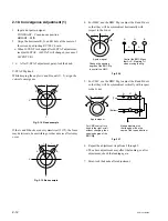
1-4-6. C Board Removal (20 inch)
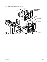
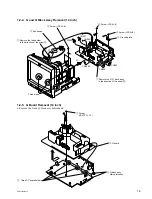
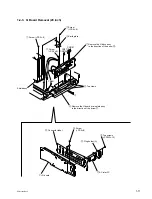
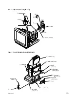
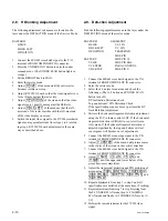
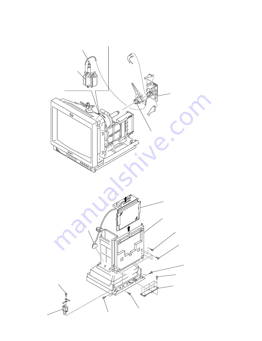
1-4-7. J and H Boards Removal (20 inch)
1
Focus lead assy
CN703
CN705
CN701
3
C board
CN702
Three claws
FBT assy
2
Fastening band assy
!/
J board
!=
H board
8
Bottom cabinet assy
2
G, B block assy
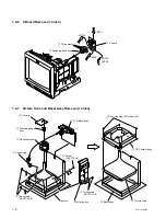
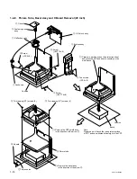
4
Four screws
(+BVTP 4
x
20)
5
Two screws
(+BVTT 4
x
12)
7
Two screws
(+BVTT 4
x
12)
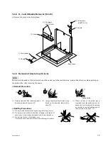
9
Two screws
(+BVTP 3
x
8)
!-
Six screws
(+BVTP 3
x
8)
3
Screw
(+PS 4
x
8)
6
Screw (+PS 4
x
8)
1
Anode cap
Summary of Contents for 2500001
Page 6: ......
Page 7: ...1 1 PVM 14L2 20L2 Section 1 Service Informations 1 1 Board Locations 14 inch C X Q B B1 G H J ...
Page 14: ...1 8 PVM 14L2 20L2 1 3 Board Locations 20 inch C Q B G J H X B1 ...
Page 22: ......
Page 40: ......
Page 50: ......
Page 56: ......
Page 60: ......
Page 141: ......
Page 161: ......


