


2-12
PVM-14L2/20L2
2-10. Convergence Adjustment (1)
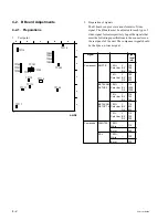
1.
Input a dot pattern signal.
CONTRAST... Conspicuous position
BRIGHT... MIN
2.
Align the horizontal R, G, and B dots at the center of
the screen by adjusting RV708/C board.
*
When H-CENT is changed after H-STAT adjustment,
readjust H-STAT. (H-STAT will change by means of
H-CENT VR.)
1
*
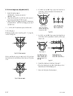
After V-STAT adjustment, paint-lock the knob.
V-STAT Mg knob
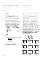
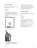
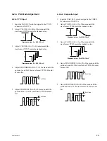
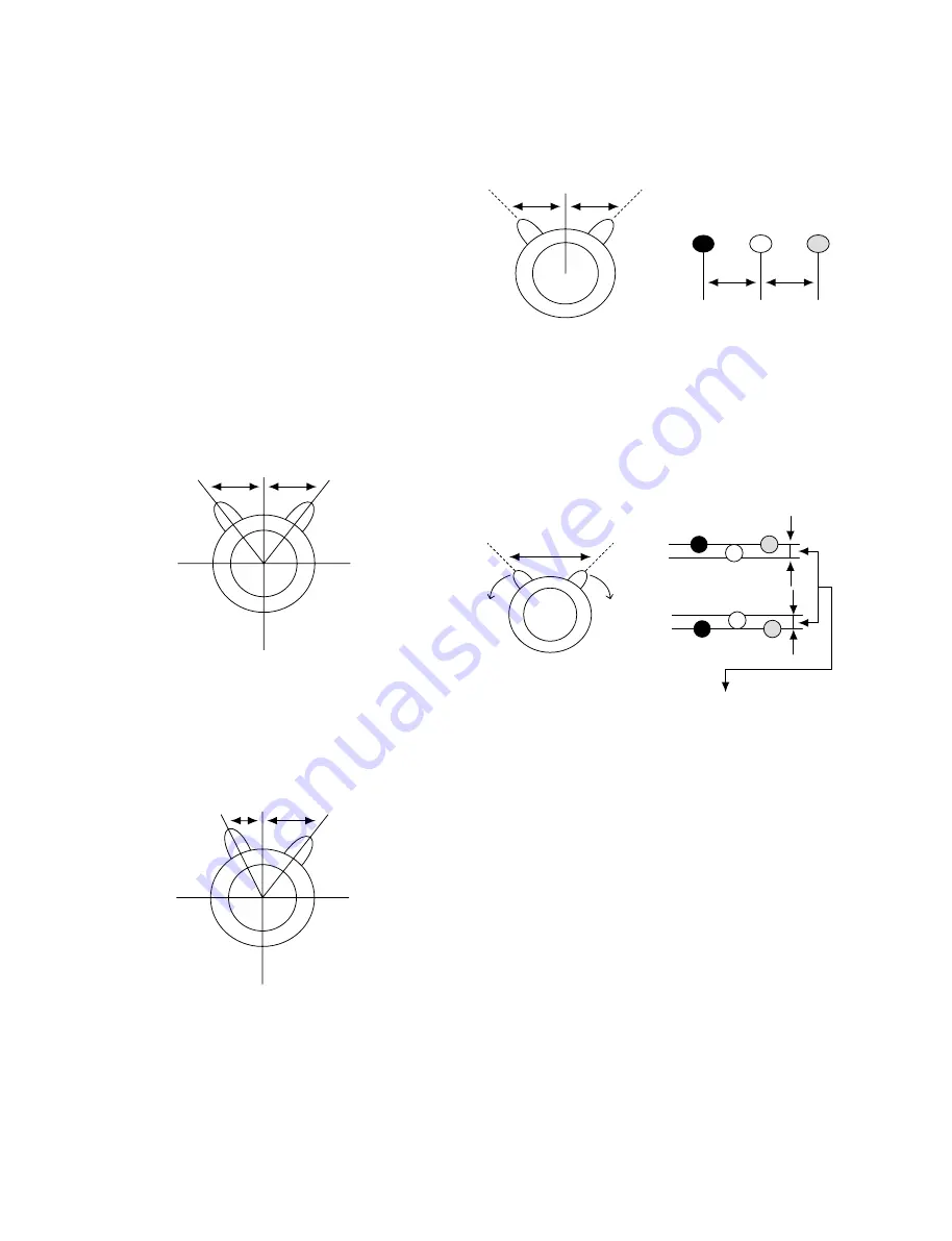
While keeping the angles A and B equal (I = I’), align the
vertical convergence.
Fig. 2-14 Good example
If the A and B knobs are not symmetrical (I
≠
I’), the focus
may deteriorate, beam striking or other adverse effects may
occur.
Fig. 2-15 Bad example
I
A
B
X
Y
I’
A
B
X
Y
I’
I
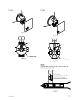
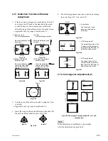
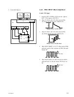
4.
For HMC, use the BMC Mg to adjust the R and B dots
so that they will be symmetrical horizontally with
respect to the G dot.
Fig. 2-16
5.
For VMC, use the BMC Mg to adjust the R and B dots
so that they will be symmetrical vertically with respect
to the G dot.
Fig. 2-17
6.
Repeat the adjustment steps from 2 through 5.
*
The above adjustment may affect the landing, so after
adjustment, check the landing again.
7.
Paint-lock the knobs after adjustment.
R
G
B
B
A
I
I’
6-pole magnet
A
A’
Change the opening
degree of the BMC Mg
to control the HMC.
Control the BMC Mg so
that A=A’. Maintain I=I’
when moving the Mg.
R
G
B
6-pole magnet
For VMC control, turn
knob to the right or left
without changing their
opening degree of the
BMC Mg.
Make adjustment so
that the gap will be the
same at the top and bottom.
Do not change.
(Top)
(Bottom)
Summary of Contents for 2500001
Page 6: ......
Page 7: ...1 1 PVM 14L2 20L2 Section 1 Service Informations 1 1 Board Locations 14 inch C X Q B B1 G H J ...
Page 14: ...1 8 PVM 14L2 20L2 1 3 Board Locations 20 inch C Q B G J H X B1 ...
Page 22: ......
Page 40: ......
Page 50: ......
Page 56: ......
Page 60: ......
Page 141: ......
Page 161: ......


