


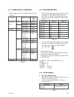


2-13
PVM-14L2/20L2
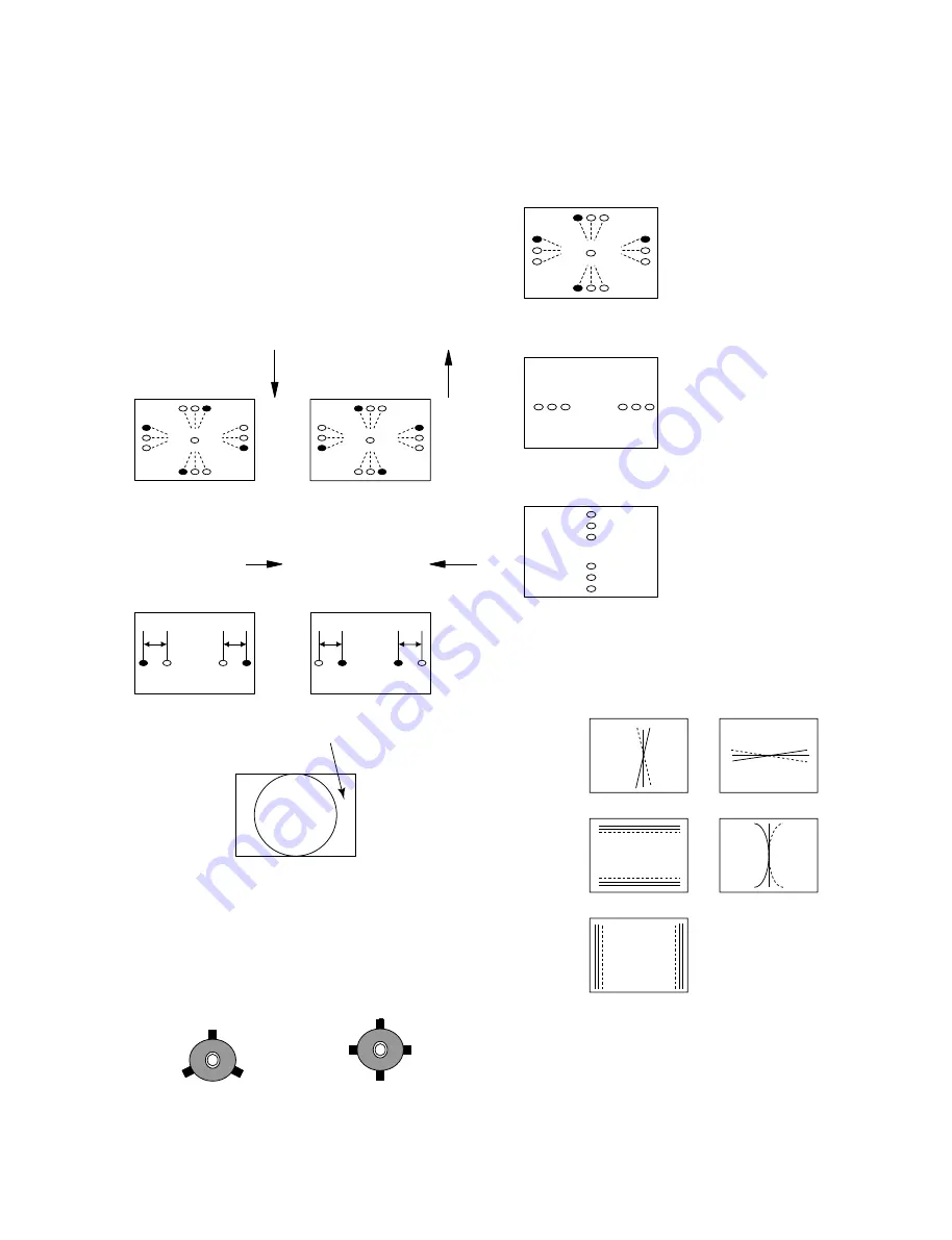
4.
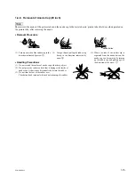
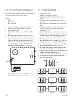
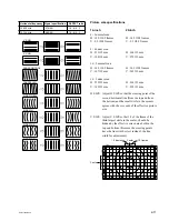
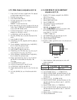
The following patterns cannot be corrected by turning
the neck. (Figs.2-25, 2-26, and 2-27)
Fig. 2-25
Fig. 2-26
Fig. 2-27
R G B
R G B
B
G
R
R
G
B
R
B
R
B
G
G
G
(G)
(G)
G
(G)
(G)
R B
R B
*
Gun rotation
The X-axis and Y-axis
beams are distorted on
both sides.
*
HCR Large (small)
The horizontal portion of the
G raster is wider (narrower)
than that of the RB raster on
both sides of the screen.
*
VCR Large (small)
The vertical portion of the
G raster is wider (narrower)
than that of the RB raster on
both sides of the screen.
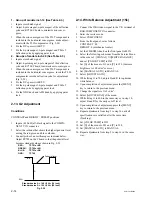
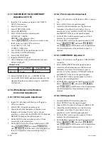
2-12. Convergence Adjustment (2)
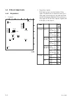
Fig. 2-28 Convergence compensation VR, coil, and
compensator
n
When adjustment is insufficient, use permalloy.
After the adjustment, use paint lock.
B
B
R
R
B
R B
G
B R
G
R
G
G
G
YCH
R
B
G
R
B
G
XCV
TLV
YBH
TLH
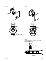
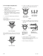
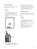
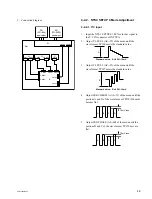
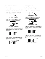
2-11. Deflection Yoke Neck Rotation
Adjustment
1.
If there are mis-convergence on both sides of X and Y
axes, move the DY neck in the direction of the arrow
so that the degree of mis-convergence satisfies the
allowable range of specification over the entire screen.
*
Applicable only to groups of models inch 14.
Fig. 2-23
2.
Turn the neck of the deflection yoke to align the V pin
vertically.
*
Applicable only to group of models inch 20.
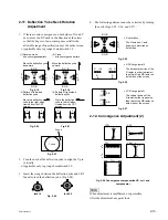
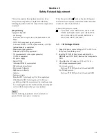
3.
Insert the wedge between the deflection yoke and CRT
funnel to lock the deflection yoke. (Fig.2-24)
Inch 14
Inch 20
Fig. 2-24
B G R
R G B
R
G
B
B
G
R
R G B
B G R
B
G
R
R
G
B
L
L
R
B
B
R
L
L
B
R
R
B
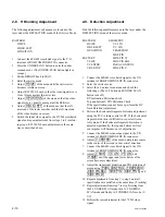
1 zone
2 zone
(1) Reverse cross
mis-convergencepattern
(2) Cross
mis-convergence pattern
Move the deflection yoke
downward.
(3) Pattern of left-sided
deflection yoke
(4) Pattern of right-sided
deflection yoke
Move the deflection
yoke to the right when
viewed from the CRT
screen.
Move the deflection
yoke to the left when
viewed from the CRT
screen.
Move the deflection yoke
upward.
Fig. 2-18
Fig. 2-19
Fig. 2-20
Fig. 2-21
Summary of Contents for 2500001
Page 6: ......
Page 7: ...1 1 PVM 14L2 20L2 Section 1 Service Informations 1 1 Board Locations 14 inch C X Q B B1 G H J ...
Page 14: ...1 8 PVM 14L2 20L2 1 3 Board Locations 20 inch C Q B G J H X B1 ...
Page 22: ......
Page 40: ......
Page 50: ......
Page 56: ......
Page 60: ......
Page 141: ......
Page 161: ......


