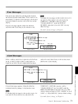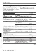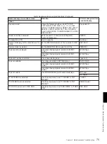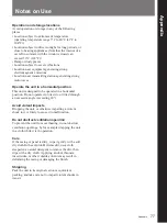
Chapter 5
Connections and Settings
67
Chapter 5
Connections and Settings
7
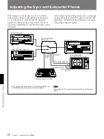
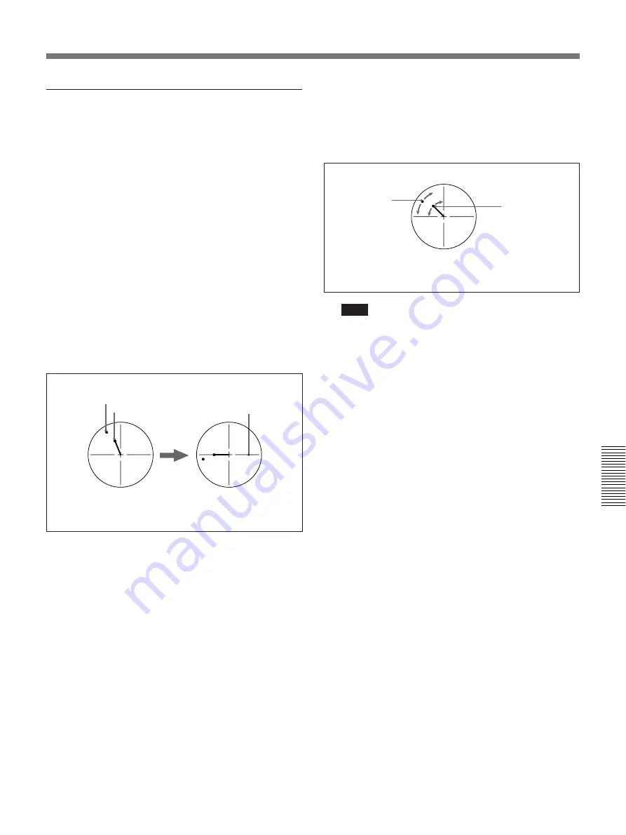
On player 1, adjust the SYNC and SC controls,
using a Phillips screwdriver, so that the output
from player 1 on channel (A) is in correct phase
alignment with the black burst signal on channel
(B).
Note
When component signals are used the subcarrier
phase indicator does not appear.
8
Output the player 2 signal from the PVE-500, and
repeat steps
6
and
7
to adjust the sync and
subcarrier phase of the output from player 2.
Subcarrier phase
Sync phase
Performing a phase adjustment operation
1
Press the SCH button on the vectorscope.
The vectorscope switches to “SCH” mode.
2
Press the B channel button on the vectorscope.
This displays the black burst signal from the
switcher.
3
Press the EXT button on the vectorscope.
This switches the vectorscope to external
synchronization mode.
4
Adjust the phase synchronization control on the
vectorscope so that the sync and subcarrier phases
are close to the reference line.
5
Output the player 1 signal from the PVE-500.
6
Press the A channel button on the vectorscope.
This displays the sync phase and subcarrier phase
(composite signals only) of the signal from player
1.
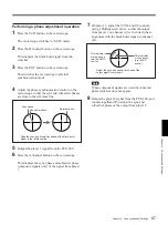
Align the sync and subcarrier phase of the black burst
signal to the reference line.
Reference line
This indicator
moves as you
turn the SYNC
control.
This indicator
moves as you
turn the SC
control.
Adjust the sync and subcarrier phase of the
output signal from player 1.


