18
AM-NX1
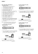
Power Supply Manual Adjustment
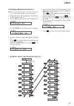
• Adjustment sequence
Adjustment must be done with the following steps.
1. VC1_LOW adjustment (item number : 741)
2. VC1_HIGH adjustment (item number : 742)
3. VC2_LOW adjustment (item number : 743)
4. VC2_HIGH adjustment (item number : 744)
5. REG1 adjustment (item number : 745)
6. REG2 adjustment (item number : 746)
7. REG3_LOW (VC2_LOW) adjustment (item number : 747)
8. REG3_LOW (VC2_HIGH) adjustment (item number : 748)
9. REG3_HIGH adjustment (item number : 749)
10. VREC_LOW adjustment (item number : 751)
11. VREC_MIDDLE adjustment (item number : 752)
12. VREC_HIGH adjustment (item number : 753)
13. ChgV_L adjustment (item number : 755)
14. ChgV_H adjustment (item number : 756)
15. ChgI_L adjustment (item number : 755)
16. ChgI_H adjustment (item number : 756)
• Setting Method of Power Supply Manual Adjustment
1. Make sure that the power supply voltage is 3V (AC adapter).
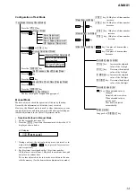
2. Select the manual mode of the test mode (see page 13).
3. Set item number.
Note:
Power supply adjustment auto item feed mode (page 23) is
available to perform the temperature Correction and Power
Supply Adjustment without entering the manual mode.
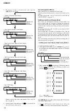
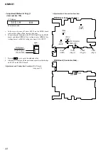
• Adjustment Method of VC1_LOW
(item number: 741)
1. Connect a digital voltmeter to the TP902 (VC1) on the MAIN
board, and adjust
[VOL +]
key (voltage up) or
[VOL --]
key (volt-
age down) so that the voltage becomes 2.35
±
0.005V.
2. Press the
–
key to write the adjusted value.
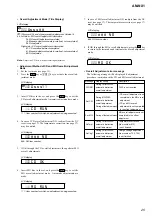
Adjustment and Connection Location: MAIN board
(see page 22)
LCD display
**
: adjusted value
V C 1 L * *
741
digital
voltmeter
MAIN board
TP902 (VC1)
TP952 (GND)
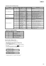
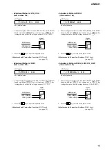
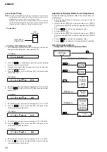
• Adjustment Method of VC1_HIGH
(item number: 742)
1. Connect a digital voltmeter to the TP902 (VC1) on the MAIN
board, and adjust
[VOL +]
key (voltage up) or
[VOL --]
key
(voltage down) so that the voltage becomes 2.75
±
0.005V.
2. Press the
–
key to write the adjusted value.
Adjustment and Connection Location: MAIN board
(see page 22)
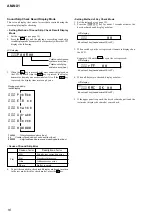
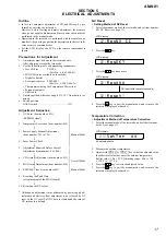
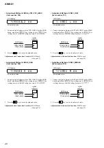
• Adjustment Method of VC2_LOW
(item number: 743)
1. Connect a digital voltmeter to the TP905 (VC2) on the MAIN
board, and adjust
[VOL +]
key (voltage up) or
[VOL --]
key
(voltage down) so that the voltage becomes 1.30
±
0.005V.
2. Press the
–
key to write the adjusted value.
Adjustment and Connection Location: MAIN board
(see page 22)
LCD display
**
: adjusted value
V C 1 H * *
742
digital
voltmeter
MAIN board
TP902 (VC1)
TP952 (GND)
LCD display
**
: adjusted value
V C 2 L o * *
743
digital
voltmeter
MAIN board
TP905 (VC2)
TP952 (GND)
Summary of Contents for AM-NX1
Page 36: ...36 AM NX1 MEMO ...

