background image

Summary of Contents for AV-3600

Page 1: ...AV 3600 V1DEOCORDER SONY CORPORATION ...

Page 2: ... DIAGRAM SERVICE in GERMANY SCHALTPLANE SERVICEANLEITUNGEN BEDIENUNGSANLEITUNGEN SERVICE MANUAL SERVICE MANUAL AV 3600 VIDEOCORDER SONY CORPORATION SCHALTUNGSDIENST LANGE Berlin 47 Postfach 47 12 20 Tel 030 404 89 PO Postgiroamt Berlin West Kto Nr 7 26 60 100 ...

Page 3: ...SERVICE MANUAL iEOC V J KL U S PAT 3 175 034 3 215 772 3 431 353 mi 3 I S i In II ii feifflMiiSL i Ski i iMii i ili SONY CORPORATION 1970 ...

Page 4: ... Bearing and Shaft Replacement 4 17 4 17 Capstan Deck Assembly Adjustment 4 19 4 18 Pinch Roller 4 19 4 19 Microswitch Maintenance and Adjustment 4 20 5 VIDEO SYSTEM ALIGNMENT 5 1 Maximum Deviation Adjustment 5 2 5 2 Carrier Leak Adjustment 5 4 5 3 Record Current Adjustment 5 4 5 4 Playback Preamplifier Adjustment 5 5 6 SERVO SYSTEM ALIGNMENT 6 1 Free Running Speed Check 6 2 6 2 Vertical Sync Sepa...

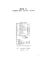
Page 5: ...udio 10 6 10 5 R R2 Voltage Regulator 10 7 10 6 SY3 Sync Former 10 7 10 7 Frame 10 8 Section Title Page 11 EXPLODED VIEWS WITH PART NUMBERS 11 1 Cabinet Assembly 11 2 1 1 2 Reel Panel and Sash 11 3 1 1 3 Head Drum Assembly 11 4 11 4 Capstan Deck Assembly and Motor 11 5 1 1 5 Tape Transport 1 11 6 1 1 6 Tape Transport 2 11 7 11 7 Record Switch Linkage 11 8 11 8 Power Supply Block and Microswitches ...

Page 6: ...perating position Horizontal only Video Characteristics Input Camera input 0 5 to 2 V p p sync negative 75 ohms unbalanced internally terminated 0 5 to 2 V p p sync negative 75 ohms unbalanced internally terminated for SONY AVC series cameras Output 1 0 V p p sync negative for a 75 ohm load unbalanced Resolution Greater than 300 lines Signal to noise ratio Greater than 40 dB Audio Characteristics ...

Page 7: ...he Function Lever to the STOP position The RECORD button is re leased and the VTR reverts to the playback mode 1 The VTR operates in the playback mode as long as the RECORD button is not depressed Note that the monitor will display a snowy raster as the playback circuits have no input signals 2 To play a prerecorded tape set the Function Lever to FORWARD The monitor will display the pictures previ...

Page 8: ...receptacle B Power Output Receptacle unswitched AC OUT 1 17V 500W Line output to power a monitor or camera Max rating 500 watts C TV Monitor Jack TV Provides all signal con nections to and from the monitor See detail D Fuse 1 5 A Contains a 1 5 ampere fuse E Audio Out Jack LINE OUT Provides an addi tional audio output feed to supply playback monitors or other audio components Signal level dB 0 775...

Page 9: ...3 c o CD C O audio input 20 dB high impedance video input 0 5 2 1 p pf sync negative 75 1 9 jn P I 2Q V 5n wrf sync to camera more than 2V p p 60 Hz ...

Page 10: ...nd this controls the amount of input signal to Q 102 R 101 and C101 accomplish pre emphasis so that the AGC circuit is effective for high frequency signals Low Pass Filter L102 L103 CI 13 The low pass filter rejects the video signals at the high end of the band such as the 3 58 MHz color subcarrier and the 4 5 MHz audio i f signal Deviation Setting and Clamp Q105 R121 D103 R126 The output of the l...

Page 11: ...r Q201 Q202 FETs and Q203 Q204 amplify the weak signals A resonant circuit in the gate of Q201 Q203 consisting of T201 T202 R201 R202 and C201 C202 resonates with the react ance of the head and increases the output from the head at the resonant frequency to provide high fre quency compensation for head to tape characteristics Inductor L203 in the collector of Q203 Q204 keeps the dc collector level...

Page 12: ... duration determined by R433 is about 24 milliseconds long enough for the circuit to ignore the next 60 Hz sync pulse Thus the multivibrator runs at 30 Hz and is triggered by every other pulse The 60 Hz sync pulse is fed to Pin 2 of MM402 and the divided 30 Hz pulse is obtained at the same Pin 2 Since the sync signal is referenced to the 30 Hz signal from 30 PG coil B 60 Hz sync pulses must be hal...

Page 13: ...ble to gate the integrated reference 30 Hz pulse at the proper position on the ramp to produce the same gating output in record or playback regardless of the dif ference in 30 Hz pulse waveshapes See Fig 2 1 R412 and R413 adjust the pulse duration delay time of MM401 in record and playback operations respectively Delayed 30 PG Pulse Shaper The delayed 30 PG negative pulse is amplified and shaped b...

Page 14: ... Q404 BASE TP 403 30 PG delay MV PB switching relations TP 412 switching pulse Q206 BASE switching pulse for B head Q20S BASE switching pulse for A head x TP 201 I TP 305 video output 8H 2 W y S 8H reference head B position of video heads pole piece Waveshaper MM404 is triggered by the trailing edge of the tracking MV output above when the TRACKING control is ON Fig 2 Timing reiations of pulse and...

Page 15: ... output appears across R515 which sets the drive to the output stage for playback The driver and output stages Q504 and Q505 func tion in the same way for both record and playback The bias erase oscillator Q506 is not energized as B to this stage is switched off in playback The sync pulse former on the SY3 Board shapes the 60 Hz ac sine wave into vertical sync pulses to lock the horizontal deflect...

Page 16: ...10 0211 REC n PB REC REC amp V2 C 0201 0203 0205 207 Q209 equalize i PBpre amp PB 0202 0204 PB pre amp 0206 FF401 wave shaper amp PB MM401 30 PG delay MV 0401 PBr REC CTL amp from 0104 I 0402 0403 jblEC MM402 5 PB sync sep puise amp LP freq divider audio input TV LINE or MIC audio head audio erase head video erase head dummy coil REC 0501 0502 J AUDIO DUB ...

Page 17: ...deo out Q310 ard video out video output to TV RF adaptor RF output to TV ANT terminal video output SY board tracking switch T ON I o o PB MM404 Q405 MV inte grator Q406 Q407 gate dc amp jbra re co 7 Q505 out D502 to I tctor audio output A board 5 Q601 Q605 regu lator Q901 Q903 VD former SY3 board _ AC117V 60 Hz VD signal to camera Fig 2 2 System block diagram 2 7 ...

Page 18: ...L OF CONTROL AND REEL PANELS 1 Pull out the SKEW control and the TRACKING control knobs 2 Loosen the two screws at the back of the Head Cover It is not necessary to remove these screws completely Lift off the Head Cover 3 Loosen the set screw in the Function Lever Allen wrench 0 1 across the flats Pull off the lever 4 Remove the screw securing the Pinch Roller Re tainer Remove the Pinch Roller Be ...

Page 19: ...ary Move the cleaning tip vertically across that part of the head surface that normally contacts the tape Noisy slip rings cause intermittent dark horizontal lines in the playback picture To clean the slip rings remove the upper drum cover on the top of the rotary head drum assembly Remove the tape from the tape path Apply a few drops of SONY cleaning fluid to the slip rings Turn on the motor for ...

Page 20: ...ed with that of a new belt from stock Replace the belt if it is inch or more longer than a new belt To install the video drum belt stand the VTR on its left side Loop the belt over the motor pulley with the shiny side of the belt inside against the pulley Grasp the bottom of the loop turn it one half turn clockwise and wrap around the pulley of the rotary head drum assembly See Fig 4 3 motor pulle...

Page 21: ...it does not fall as you withdraw the two screws 4 Carefully lift the top of the drum assembly and fold it back Place the drum top carefully on the reel panel See Fig 4 5 Loosen these screws v x slip ring f y Loosen these CJ w J screws Ttx V Vu l Fig 4 4 Preparation for video head replacement Fig 4 5 Video head assembly removal CAUTION Do not touch the PG pole pieces Position the rotary head platfo...

Page 22: ...he drum holder so that top surface of the upper drum is even with that of the drum holder Fig 4 6 Position of the head assembly 10 Install the two P 4 x 8 screws and washers Rotate the head assembly gently to the left and right until it is approximately in the center of the angular play permitted by the mounting screws Tighten the screws alternately applying torque gradually until the screws are t...

Page 23: ...y can not be maintained Video Head B not A should be adjusted so that it is correctly aligned with respect to Video Head A This adjustment requires the use of the SONY Alignment Tape and the four adjusting screws shown in Fig 4 7b The adjusting screw has a tapered head which bears against the base of the head when turned clockwise thus forcing the head to move laterally The thread of this screw is...

Page 24: ...B identified by red paint on the outer edge of the beam to the adjusting position shown in Step 5 10 First loosen the a adjusting screw about a quarter turn counterclockwise and tighten the b adjusting screw a quarter turn clockwise See Fig 4 7b 11 Play back the tape Check the picture on the monitor screen 12 If the dihedral error does not change repeat Steps 9 10 and 1 1 until a change is visible...

Page 25: ...es not proceed to Steps 6 through 10 and then repeat Steps 1 to 3 6 Set the Function Lever to the FORWARD po sition 7 Check the distance between the Tape Guide Pin on the Tension Arm and the extreme left edge of the drum deck as shown in Fig 4 9 It should be about 1 mm Swing the Brake Band as needed to obtain the correct spacing 8 Check for clearance between the hole in the chassis and Item shown ...

Page 26: ...ng Plate Assembly using the original screws A and B in Fig 4 10 a The spring on screw A goes between the head of the screw and the top of the mounting plate Tighten screw A and adjust screw B azimuth adjust as follows 7 Thread the SONY Alignment Tape and play the first section Test Pattern Connect an AC VTVM to the LINE OUT connector on the Connector Panel and terminate this connector with a 1 00 ...

Page 27: ...wind Idlers for excessive or uneven wear Inspect the driving surface of the Supply Reel Assembly Clean away any oil or debris from all driving surfaces 3 Set the Function Lever to STOP Check that the Right Rewind Idler is clear of the Idler Stopper by 0 5 to 1 mm See Fig 4 13 If this condition does not exist bend the Idler Stopper with a pair of pliers 4 Check that the contacting surfaces of the R...

Page 28: ...capstan motor pulley take up Idler A take up reel table T W S X L i i in aJI H take up cam ass y Fig 4 12 Take up idler height Fig 4 13 Rewind idler repiacemen t 4 10 ...

Page 29: ...shaft Next rotate the directional brake clockwise until the point faces to the right 3 o clock Position the idler shaft so that the idler can be dropped onto the shaft Re lease the directional brake Install the fiber washer and the Retaining Ring 1 0 Place a drop of oil on the shaft of the Right Re wind Idler Install the Right Rewind Idler the fiber washer the push rod and the Retaining Ring in th...

Page 30: ...Set the Function Lever to PAUSE 6 Repeat the procedure described in Step 2 for the direction indicated by g in Fig 4 14 It should be more than 800 g cm 7 If necessary bend the portion of the Pause Brake Lever identified by 5 with a pair of pliers Take Up Brake Lever Check 1 Set the Function Lever to STOP 2 Check that the top end of the Brake Lever is dis engaged from the Function Selector Cam by a...

Page 31: ...ng is applied before the Take Up Reel Table stops running 4 Thread a tape on the VTR and advance it until all the tape is on the Take Up Reel Table Move the Function Lever from REWIND to STOP Check that the tape stops without excess slack If it does not bend the Brake Lever with a pair of pliers There should still be at least 0 5 mm clearance between the Brake Lever and the Takeup Reel Table Place...

Page 32: ...tor 3 Remove the drive belt for the Rotary Head Drum Assembly 4 Inspect the lower drive pulley on the motor shaft and note the position of the fan on the shaft The bottom of the fan hub should be almost flush with the lower end of the motor shaft 5 Loosen the set screw in the lower drive pulley and remove the drive pulley and fan Note Do not remove the gray plastic fan from the lower drive pulley ...

Page 33: ... in each mode 8 Make sure that the sensing wire operates smooth ly without touching the Tape Guide or the Taper ed Guide 4 16 CAPSTAN BEARING AND SHAFT RE PLACEMENT A worn Capstan Bearing results in noisy opera tion a squealing sound from the capstan When it be comes necessary to replace the Capstan Bearing the Capstan Shaft assembly including the Flywheel must be replaced as well Proceed as follo...

Page 34: ...rt the Capstan Bearing into the Capstan Deck and put the Capstan Bearing Retainer on the Cap stan Bearing Tighten the three screws that secure the retainer to the chassis 13 Place a few drops of oil on the inner surface of the bearing 14 Put the Spacer on the Capstan Shaft Insert the shaft into the Capstan Bearing 15 Hold the Flywheel with one hand and slip the Oil Ring Retainer and Oil Ring onto ...

Page 35: ...e over the motor leads Solder the motor leads to the following tie points black terminal 3 of the terminal strip white terminal 5 of the terminal strip green common lug of C701 19 Install the Rotary Head Drum Assembly drive belt 20 Operate the motor and check the FORWARD FAST FORWARD and REWIND operations Check the running position of the lower drive belt as directed in Section 4 4 5 14 RECORD BUT...

Page 36: ... position after about 1 second Repeat this check with tape threaded properly The motor should remain on when the Function Lever is set to FORWARD PAUSE FAST FORWARD and REWIND Set the Function Lever to STOP and depress the RECORD button The motor should turn on Thread the tape on the VTR Make sure that the motor is not shut off by a slight overshoot of the tape sensing wire If the aforementioned c...

Page 37: ...ower end of the Drum Mounting Deck is more than 1 5 mm See Fig 4 23 If it needs adjustment bend A in Fig 4 21 with a pair of pliers Recheck Pinch Roller Pressure as described in Section 4 18 4 Switch the Function Lever through all modes 4 18 PINCH ROLLER Pinch Roller Replacement Replace a worn or damaged Pinch Roller as follows 1 Place the VTR in the STOP mode 2 Remove the Pinch Roller Retainer an...

Page 38: ... See Fig 4 24 Pull the scale in the direction indicated by the arrow Check the read ing when the Pinch Roller just leaves the Capstan Shaft It should be between 1 5 and 2 2 kg 4 19 MICROSWITCH MAINTENANCE AND AD JUSTMENT 1 Set the Function Lever to the STOP mode Make sure that the switching button of the micro switch SW 4 under the chassis beneath t Function Lever is in the center of the Cam See F...

Page 39: ...ed Test Tape g Video Signal Generator h R F Signal Generator Eico 380 RCA WR 50B or equivalent The following test equipment is required for use at Factory Service Stations a TV monitor b Oscilloscope c Video Signal Generator d Audio Generator e AC VTVM Audio SONY CVM 51UW UWP Tektronix 422 561 A vith 3A1 3B3 plug ins or equiva lent Telemet 3502A1 Stairstep Generator or equivalent Heath IGW 72 Hewl...

Page 40: ...Hz as indicated on the scope screen 3 2 MHz can be measured as follows a Adjust scope time base for 0 5 isec per divi sion calibrated b Set scope controls to obtain a stable trace A correct carrier frequency of 3 2 MHz is indicat ed when there are 16 complete square waves in ten divisions Set R126 to produce this indication See Fig 5 2a 7 Set up the E to E mode using a stairstep signal of 1 0 volt...

Page 41: ...oltage level of the trace on CHANNEL 2 with reference to the trace on CHANNEL 1 as obtained is Step 7 See Fig 5 2b Mark the scope graticule 9 Apply a stairstep signal of 1 0 volt p p to the TV jack See Fig 5 la 10 Readjust R126 Carrier Frequency so that the sync tip part of the waveform corresponds to the position of the trace measured in Step 6 See Fig 5 2c 11 Adjust R121 Deviation Set so that th...

Page 42: ... Carrier Balance and R326 Freq Doubler Carrier Balance for minimum carrier leak herringbone Repeat both adjustments 4 Adjust R148 Modulator Carrier Balance and CI 22 Modulator Carrier Balance for minimum carrier leak Repeat both adjustments t 5 Repeat Steps 3 and 4 6 Make a recording 7 Play back the tape and observe the picture If carrier leak is still visible trim up R305 and R326 to minimize car...

Page 43: ...nce and Playback Equaliza tion Frequency characteristics of the playback ampli fiers are adjusted to equalize head to tape characteris tics and to obtain the desired overall frequency response Test PointI Board Adjust for TP 201 V2 PBrf output Correct frequency response as shown in Fig 5 4 A B C 1 3 5 4 Adjustment Board C201 R201 V2 Head Resonance ChA C202 R202 V2 Head Resonance ChB L204 V2 PB Equ...

Page 44: ...noted in Step 4 that is amplitude at 500 kHz _ J_ amplitude at 4 5 MHz 4 Note the amplitude at 500 kHz 7 Lift the orange lead of the cable to the B head at the V2 Board and connect the Rf Signal Generator in place using the resistive network as in Steps 1 and 2 of Preparation 8 Adjust C202 and R202 of Channel B in the same manner as in Steps 1 to 6 Midrange Equalization Adjustment 9 Tune the Rf Si...

Page 45: ...Drum Speed Control System 30 Hz PULSE ADJUSTMENT Sec 6 4 i 30 PG PULSE LOCK PHASE ADJUSTMENT I Sec 6 5 SERVO RESPONSE TIME ADJUSTMENT Sec 6 6 I PLAYBACK SERVO CHECK PB Sec 6 7 i 30 PG PULSE POSITION CHECK 30 PG Coil Position Sec 6 8 I 30 PG PULSE PHASE CHECK Sec 6 9 i i SERVO REFERENCE SERVO REFERENCE DELAY MV REC DELAY MV PB Sec 6 10 Sec 6 11 i 1 TRACKING CONTROL CHECK Sec 6 12 Camera Control Sys...

Page 46: ...r Test Point Board TP 404 TP 405 TP 406 SV Check Waveforms shown in Fig 6 1 Adjustment None Signal Source Telecast signal Equipment Required 1 Oscilloscope 2 TV monitor Procedure 1 Set up the E to E mode using a telecast signal 2 Connect the scope to TP 404 TP 405 and TP 406 and check that the waveforms shown in Fig 6 1 are correct 3 If they are incorrect check and troubleshoot the sync separator ...

Page 47: ... REC E E mode Adjust for Adjustment Board Signal Source Equipment Required See Fig 6 4 R454 SV Lock Phase Telecast signal 1 Oscilloscope 2 TV monitor Procedure 1 Set up the E to E mode using a telecast signal 2 Connect the scope to TP 410 3 Set the scope for 5 ms cm horizontal sweep and pull out the 5X magnifier Each division on the time base now represents 1 msec 4 Adjust the POSITION control on ...

Page 48: ...peat Step 3 after each adjustment ofR451 Note Clockwise rotation of R451 shortens the lock in time but increases hunting Counterclockwise rotation decreases hunting but lengthens lock in time 6 7 PLAYBACK SERVO CHECK Check that the correct CTL Control track pulses are reproduced for the servo system in the Playback mode Equipment Required 1 Oscilloscope 2 TV monitor Procedure 1 Make a recording of...

Page 49: ...CHECK in Sec 6 9 If it is not correct reposition 30 PG Coil A which is mounted at the front of the scanner at the six o clock position See Fig 6 8 Be sure the motor is off when making this adjustment Proceed as follows 7 Stop the motor release the RECORD button and allow the heads to stop turning Loosen the screw securing 30 PG Coil A and 9 Fig 6 8 30 PG Coils A and B reposition the coil If T in F...

Page 50: ... ms cm 4 Turn the VARIABLE control of the scopes time base counterclockwise from the CALIB RATED to the UNCALIBRATED until two pulses can be seen at the same time on the scope 5 Pull out the 5X magnifier and adjust the HORI ZONTAL POSITION control to observe the leading edge of either pulse See Fig 6 9 6 Check that the leading edge of a pulse does not overlap the trailing edge of the previous puls...

Page 51: ...tor adjustmen t PB mode Adjustment Board R412 SV Lock Phase Signal Source Telecast signal Equipment Required 1 Oscilloscope 2 TV monitor Procedure 1 Make a recording of a telecast signal 2 Play back the tape 3 Connect the scope to TP 403 4 Adjust R412 PB Lock Phase to produce 1 9 ms pulse width as shown in Fig 6 11 6 12 TRACKING CONTROL CHECK This test checks the range of the variable tracking con...

Page 52: ...cope Procedure 1 Turn on the Videocorder with or without an input signal 2 Connect a 75 ohm resistor between Pin 2 and Pin 6 of the 6 pin CAMERA receptacle 3 Connect the scope to Pin 2 4 Check that the output is as shown in Fig 6 13 5 If it is not check and troubleshoot the SY3 Board mounted behind the connector panel 75n Vo o u V J o y CAMERA receptacle 7 4H 1 m more than 2V p p T b L Fig 6 13 Ve...

Page 53: ...ure and sequence is shown in Chart 7 1 AUDIO CTL HEAD AZIMUTH AND TILT ADJUSTMENT Sec 7 1 PLAYBACK LEVEL ADJUSTMENT Sec 7 2 BIAS ERASE OSCILLATOR CHECK Sec 7 4 AUDIO RECORD BIAS SETTING Sec 7 5 LINE OUTPUT LEVEL CALIBRATION Sec 7 3 Chart 7 1 Audio system alignment 7 1 ...

Page 54: ...1 Connect the ac VTVM to TP 502 using a 100 k 2 load resistor as shown in Fig 7 2 2 Play back the SONY Alignment Tape 1 kHz tone 3 Adjust R515 Playback Level to obtain a read ing of dB 0 755 V on the VTVM A V 3600 lA TP 502 on A Board 100kSl 777 777 VTVM Fig 7 2 Audio playback level and frequency response adjustment set up 7 3 LINE OUTPUT LEVEL Record mode Record Level CALIBRATION Test Point Adjus...

Page 55: ...that the frequency is between 80 kHz and 100 kHz 12 5 jus and 10 is If the scope waveform does not conform to rated specifications check and troubleshoot the erase oscillator circuit Test Point Adjust for Adjustment Signal Source Equipment Required Procedure TP 504 Audio Head Input Output 22 volts C532 Bias L401 Dummy Coil None required 1 AC VTVM 2 Blank tape 1 Thread the tape and set up the Recor...

Page 56: ...Procedure 1 VOM 2 Variac or adjustable transformer 1 Set the ac input voltage to 117 volts using the Variac or adjustable transformer 2 Connect the VOM between TP 601 and ground 3 Adjust R604 for a reading of 28 volts dc For Sets bearing Serial No 12 201 and higher Fig 8 1 A chassis mark These sets are identified by the letter A stamped on the chassis as shown 4 Connect the VOM between TP 602 and ...

Page 57: ...SECTION 9 PRINTED CIRCUIT BOARD AND SCHEMATIC DIAGRAMS Semiconductor Electrodes 2SA611 O B 2SD28 2SK19Y D S G 2SK23 S 6 D CF 011B CV 001 RD4A RD13A cathode cathode mark anode cathode mark 6 5 4 3 2 9 1 ...

Page 58: ...CO 0 sv SERVO BOARD SY3 SYNC SEPARATOR AUDIO BOARD RorR2 VOLTAGE BOARD REGULATOR sw SWITCH BOARD LIMITER DEMOD BOARD MOD REC PB AMP BOARD ...

Page 59: ...9 1 V2 IVJOD REC PB AMP PRINTED CIRCUIT BOARD CONDUCTOR SIDE 2Vp p S9 3 ...

Page 60: ...V2 MOD REC PB AMP PRINTED CIRCUIT BOARD COMPONENT SIDE 9 4 ...

Page 61: ... V1 LIMiTER DEfVlOD PRINTED CIRCUIT BOARD CONDUCTOR SIDE J 2MHz at no signal R335 VIDEO OUT LEVEL R305 CARRIER BALANCE R326 CARRIER BALANCE TP 303 3 2 MHz at no signal T L2Vp p LLL1 3 2MHz at no signal 9 5 ...

Page 62: ...V1 LIMITER DEiVSOD PRINTED CIRCUIT BOARD COMPONENT SIDE C306 C305 0302 c303 C3Q2 Q30I Hi itlii D303 ISS925 9 6 ...

Page 63: ...9 3 SV SERVO PRINTED CIRCUIT BOARD CONDUCTOR SIDE TP 405 T l 3Vp p Li 60Hz REC mode 30 Hz TP 406 il l5Vp p 60Hz M REC mode 30Hz PB mode TP 409 T 16 Vp p 1 9 1 ...

Page 64: ...SV SERVO PRINTED CIRCUIT BOARD COMPONENT SIDE 9 8 ...

Page 65: ...A AUDIO PRINTED CIRCUIT BOARD COMPONENT SIDE U u R513 100K A A 9 10 ...

Page 66: ...9 4 A AUDIO PRINTED CIRCUIT BOARD CONDUCTOR SIDE 9 9 ...

Page 67: ...SD82 m R609 5600 R6I0 5K B R604 5K B PD604 RD4A or IS994 C607 o ri o47 i R wQ605 3I8A R607 o uul_o 7500 W R608 3300 R606 300 I 2W MC606 I 10 6 25V Q6C Q604 2SC756 R VOLTAGE REGULATOR Serial number up to 12 200 PRINTED CIRCUIT BOARD CONDUCTOR SIDE C60J 3 POWER XFORMER 0 D601 SA 2Z C602 022 R604 5K 0602 B B h 9 11 ...

Page 68: ...AGE REGULATOR PRINTED CIRCUIT BOARD Serial number 12 201 and higher COMPONENT SIDE D6034 RD T3A1 Q604 2SC756 R VOLTAGE REGULATOR Serial number up to 12 200 PRINTED CIRCUIT BOARD COMPONENT SIDE C603 10 50V 9 12 ...

Page 69: ...9 6 SY3 VERTICAL SYNC FORMER PRINTED CIRCUIT BOARD CONDUCTOR SIDE D90I ISI555 C90 015 0 05 C902 R 03 22 430 R90I 3K TOOf POWER XFORMER 10V AC TOO POWER XFORMER 10V AC I CN4 CAMERA VD OUTPUT B 28V 9 13 ...

Page 70: ... C904T 0068 Q902 2SC403A R905 v IOK 9 3 I Q R904 S C903 3300 f 33 1 25V R902 2K Q90I 2SC403A R90 I 3K I O C90I 015 SW SWITCH BOARD CN5 MIC IN S R501 Aboard AUDIO INPUT w xj f l T i l R00 75 T R002 1 75 R003 75 4 i M 3 R006 JOOK z CNS VIDEO IN _BLK_ BLK SW7 7 SV board CN3 TV VIDEO INPUT I CN3 n 8 TV ON3 n 7 9 14 ...

Page 71: ... H Li R2i4 2200 ER2I8 100 R22I 2200 I _ 1 ZL C2I5 I 2W SW6 I o C 3J 5 O DARK CU tf SW i e o A 1ST LIMITER R306 4 33K Q3022SC3I8A 2N0 LIMFTER R303 OK j R309 O 5 C306 500 R306 soo f ft 01 j icr Q3032SC4O3A 3RD LIMITER Q3042SC4 4TH R3I7 330 2 I 2W r R3 56 R3II 75K CARRIER BALANCE 03062SC403A RF AMP Vi 03072SC403A Q3082SC403A VIDEO AMP R342 10k R344 390 I 2W VIDEO OUT LEVEL MM40I cv ooi 30 PG DELAY MV...

Page 72: ...C voltages measured from point indicated to chassis with a VOM 20 kn volt and with no signal input All voltage readings obtained may vary slightly due to normal component tolerances All switches are in the Record mode Design and specifications subject to change without notice SONV VIDEOCORDER SCHEMATIC DIAGRAM AV 3600 Serial No 12 201 and higher 905 ...

Page 73: ...a g 3 1 XZTZ 1 r ym fW 2v M SW NO FUNCTION SWI POWER SW2 SHUT OFF SW3 MOTOR REC BUTTO SW4 MOTOR FUNCTION S SW5 TV LINE CAMERA SEL SW6 PB E E SELECT SW7 PB EE SELECT SW8 PB E E SELECT SW9 RECORD 3e 9 16 ...

Page 74: ...IPB mod SPECIFICATIONS OF SWITCHES to SW NO FUNCTION MODE SW 1 POWER OFF SW2 SHUT OFF ON SW3 MOTOR REC BUTTON OFF SW4 MOTOR FUNCTION SELECT OFF SW5 TV LINE CAMERA SELECT LINE SW6 PB E E SELECT E E SW7 PB EE SELECT E E SW8 PB E E SELECT E E SW9 RECORD OFF 50V Q6032SC3I8A Q6022SC756 TT I 6 poT T SY3 R909 510 A R907 iok Q902 2SC403A 28 l_ Q90I2SC403A 09032SA6II SW2 SW4 SvV3 SHUT OFF MOTOR SW MOTOR SW...

Page 75: ...pF 3 3 47 20 pF 20 pF 0 01 0 01 0 047 0 047 0 1 0 01 0 1 0 1 10 50V 16V 16V 16V 16V 25V 25V 25V 25V 25V 25V 10 50V 16V 25V 16V 10 50V 25V 10 50V 10 50V 50V 10 50V 25V 25V 50V 50V 50V 50V 50V 50V 50V 50V silvered mica elect elect elect elect elect elect elect elect elect elect silvered mica elect elect elect plastic film elect silvered mica silvered mica trimmer mylar silvered mica elect elect trim...

Page 76: ...y2w 100k 3300 10 k adjustable linear Ik 100 Ref No Part No Description R141 1 242 661 11 330 R142 1 242 649 11 100 R143 1 242 649 11 100 R144 1 242 661 11 330 R145 1 242 661 11 330 R146 1 242 685 11 3300 R147 1 242 685 11 3300 R148 1 221 494 11 500 adjustable linear R151 1 242 659 11 270 R152 1 242 680 11 2k R153 1 242 655 11 180 R154 1 242 675 11 1200 R155 1 221 497 11 5 k adjustable linear R201 ...

Page 77: ...0V 50V 50V 50V 50V 16V 680 pF 10 50V 47 25V 47 16V 91 pF 5 50V 91 pF 5 50V 47 47 47 100 470 470 6 3V 16V 16V 25V 16V 16V mylar mylar mylar ceramic mylar mylar mylar mylar ceramic mylar mylar ceramic mylar elect plastic film elect elect silvered mica silvered mica elect elect elect elect elect elect Ref No Part No Description DIODES D301 1S1925 D302 1S1925 D303 1S1925 D304 1S1925 D305 1S1925 D306 I...

Page 78: ...pF j UF Tolerance of all electrolytic elect capacitors as follows less than 4 7 jUF 10 150 4 7 JUF and higher 10 100 1 425 544 11 Transformer TD C401 1 121 391 11 1 50V elect C402 1 121 391 11 1 50V elect C403 1 121 403 11 33 16V elect C404 1 105 821 12 0 001 50V mylar C405 1 105 841 12 0 047 50V mylar C406 1 121 391 11 1 50V elect C407 1 121 469 11 10 10V elect C408 1 121 410 11 47 25V elect C409...

Page 79: ... 705 11 Description R416 22 k R417 1 242 685 11 3300 R418 1 242 680 11 2k R419 1 242 668 11 620 R420 1 242 744 11 910 k R421 1 242 712 11 43 k R422 1 242 690 11 5100 R423 1 242 690 11 5100 R424 1 242 697 11 10 k R425 1 242 697 11 10 k R426 1 242 697 11 10 k R427 1 242 697 11 10 k R428 1 242 697 11 10 k R429 1 242 697 11 10 k R430 1 242 673 11 Ik R431 1 242 709 11 33 k R432 1 242 709 11 33 k R433 1...

Page 80: ...V mylar C530 1 105 681 12 0 047 10 50V mylar C531 1 121 373 11 33 25V elect C532 1 141 034 21 30 200 pF trimmer C533 1 129 707 11 2700 pF 10 600V film C534 1 121 472 11 10 25V elect C535 1 105 671 12 0 0068 10 50V mylar DIODES D501 1T22M D502 D503 1T22M 1S358 L501 1 407 200 11 L502 1 407 240 11 L503 1 407 210 11 INDUCTORS 3 3 mH 22 mH variable 22 mH TRANSISTORS Q501 2SC631 Q502 2SC631 Q503 2SK23 Q...

Page 81: ...lect C605 1 105 821 12 0 001 50V mylar tC606 1 121 398 11 10 25V elect fC607 1 121 409 11 47 16V elect tC608 1 105 837 12 0 022 50V mylar Ref No Part No Description DIODES D601 SA2Z D602 SA2Z D603 RD13A fD604 RD4A TRANSISTORS Q602 2SC756 Q603 2SC318A tQ604 2SC756 tQ605 2SC318A RESISTORS All resistors in ohms 5 W fixed carbon unless otherwise indicated k 1000 M 1000 k R601 1 242 694 11 7500 R602 1 ...

Page 82: ... 507 053 04 Mini Jack CN6 1 507 053 04 Mini Jack CN7 1 507 053 04 Mini Jack CN8 1 526 071 41 UHF connector CN9 1 526 071 41 UHF connector CN10 1 507 053 04 Mini Jack CN11 1 507 290 12 6 pin socket RF adaptor 1 51 7 003 00 Socket lamp TRANSISTOR Q601 2SD82 RESISTORS R001 1 242 646 11 75 5 W carbon R002 1 242 646 11 75 5 y 4 W carbon R003 1 242 646 11 75 5 W carbon R004 1 242 745 11 1 M 5 KW carbon ...

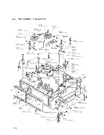
Page 83: ...Truss Head Screw f R Round Head Screw F Flat Fillister Head Screw Q SC Set Screw E Retaining Ring E Washer W Washer SW Spring Washer LW Lock Washer N Nut Example I Type of Slot P3xl0 T T7 1 LI Length in mm L l l Diameter in mm D l Type of Head 0 dp 1 5 1 ft IdI JdU All screws conform to ISO standards unless otherwise noted Scale I MlllMiiliml mi Ji 25 4 millimeters I i I i I i 1 1 I i h 1 1 I i I ...

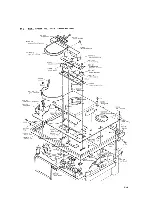
Page 84: ...3 050 retainer 1 reel 3 613 051 retainer 2 reel 3 613 197 plate nut clasp 13 437128 01 foot A cabinet 0 051 263 foot rubber P4x25 Notes Items marked with f are included in the Cabinet Assembly X 36210 01 Items marked with are included in the Cabinet Cover Assembly X 36215 01 1 3 613 045 retainer grille 8 11 2 ...

Page 85: ...L PANEL AND SASH EXPLODED VIEW 3 621 020 SONY emblem f 3 621 019 ornamental panel head cover X 36210 10 cover ass y A head 3 613 158 01 cover red pilot lamp 3 613 181 ornamental plate pushbutton escutcheon 11 3 ...

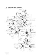
Page 86: ... ASSEMBLY EXPLODED VIEW Video Head Drum Assembly 94 5517 02 60 Hz 3 601 342 label CAUTION 3 621 514 label PATENT No P3x6 W3 small 3 612 922 bracket PG coil W 2 small 1 419 019 81 coil 60 PG 1 454 019 brake coil 11 4 ...

Page 87: ...OTOR EXPLODED VIEW 3 418 191 screw audio CTL head 3 005 001 spring head azimuth adj 3 607 064 spacer audio CTL head 3 601 291 spacer audio CTL head 8 821 221 audio CTL head PP30 21Q2A 3 613 150 belt drum 3 601 090 fan motor P3x6 11 5 ...

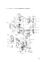
Page 88: ... 25 idler ass y rewind 0 027 200 spring rewind idler brake 3 419 093 brake S rewind idler X 00270 09 arm ass y C idler 3 418 077 spring take up idler shaft X 361 30 20 retainer 3 A board 3 613 146 reinforcement deck support 3 613 133 retainer 1 VI board 3 621 045 cam leaf switch 3 613 134 cam motor switch selector PS 2 6 x 6 11 6 ...

Page 89: ... belt tape counter 3 607 749 shaft skew control set screw 3x3 3 607 754 gear 1 skew control X 36210 08 bracket ass y A skew control X 36040 30 drum ass y take up 3 601 037 washer fiber thrust bearer 3 613 190 spindle take up reel 3 613036 mount take up reel spindle X 34 194 07 lever ass y B take up reel brake 3 613 216 spring take up brake 0 051 220 spring B pull rod 0 037 249 split nut 3 621 034 ...

Page 90: ...tton select 3 613 164 screw slide switch link holder 3 613 210 spring 2 slide switch push 3 613 107 slide plate slide switch 3 604 152 selector AUDIO DUB 3 604 151 spacer AUDIO DUB selector 3 613 214 spring 2 AUDIO DUB selector X 361 30 12 stopper ass y 1 RECORD button 3 613 103 plate A AUDIO DUB button 3 613 105 lever RECORD set release 3 613 112 puflrod 1 slide switch 3 613 137 spring RECORD AUD...

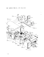
Page 91: ...063 s insulator lug terminal 1 5 p 1 536 179 terminal strip 5 p 3001 706 02 _ clamp harness W3 P3x8 4 3 407 040 pulley tape counter belt 3 613 122 shaft tape counter pu le 3 613 121 spacer tape counter puilev 3 613 186 pulley A tape counter 3 613 120 _ bracket counter pulley A LW3 N30 P3x6 119 ...

Page 92: ...ort front left deck ass y PS3x6 3 613 132 retainer 2 SV board 3 621 069 collector static electricity PS3x6 3 613 133 retainer 0 SVboa rd 3 613 146 reinfocement deck support 3 621 060 holder 2 harness 2 3 12 PS3x8 3 621 513 ornamental plate connector panel 11 10 ...

Page 93: ... medium 7 623 1 12 12 5 mm dia medium 7 623 113 12 6 mm dia medium 7 623 207 22 Spring Washer 2 6 mm dia 7 623 208 22 Spring Washer 3 mm dia 7 623 210 22 Spring Washer 4 mm dia 7 623 407 05 Star Washer external 2 6 mm dia 7 623 408 05 Star Washer external 3 mm dia 7 623 908 02 Fiber Washer 3 mm dia 7 623 908 04 Plastic Washer 3 mm dia 7 624 102 01 E Washer 1 5 Part No 7 624 105 01 7 624 106 01 7 6...

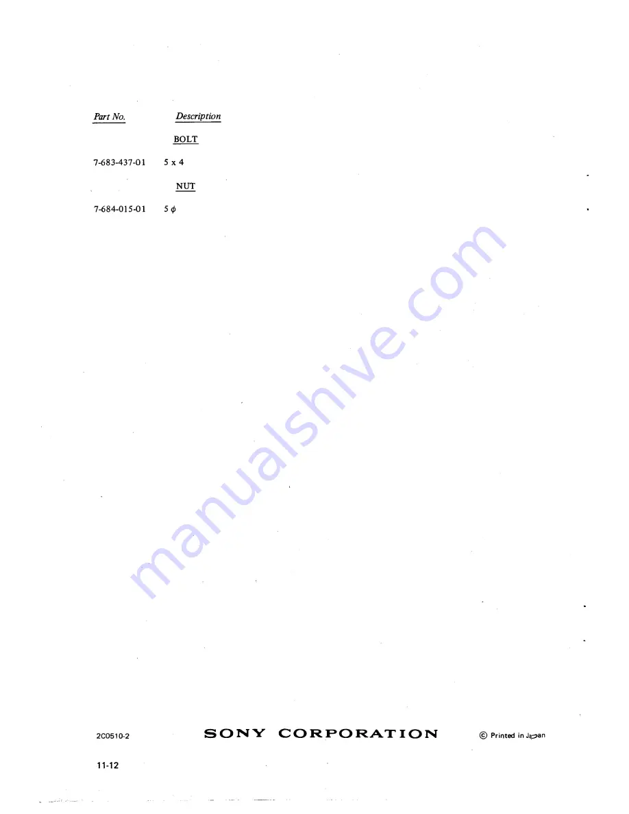
Page 94: ...Part No Descrip BOLT nion 7 683 437 01 5x4 NUT 7 684 015 01 50 2C0510 2 11 12 SONY CORPORATION Printed inJ pan ...

Page 95: ...To shift up the FM Carrier Frequency for 100 kHz Sync Tip frequency from 3 2 MHz to 3 3 MHz White Peak frequency from 4 6 MHz to 4 7 MHz 4 To add to the Video Output Amplifiers Q307 Q308 in VI board a compensation circuit for middle frequency range 1 6 MHz to 2 MHz 5 To rise up the frequency response of the PB Amplifier V2 board for about 2 dB which has been flat up to high frequency 6 To decrease...

Page 96: ... 5 1b White dip and dark clip ieveis Procedure B page 5 3 5 Adjust R126 Sync Tip Carrier Freq for a stable trace of 3 3 MHz 6 This trace indicates the dc level of the modulator input required to produce 3 3 MHz at the modulator output 7 Readjust R126 for 4 7 MHz as indicated on the scope A correct frequency of 4 7 MHz is indicated when there are 23 5 square waves in ten divisions when the time bas...

Page 97: ...01 V2 Board Sync the scope externally from TP 412 SV Board Set the scope time base to 5 msec cm Four markers in the playback rf signal indicate the 1 MHz 2 MHz 3 58 MHz and 4 5 MHz points 3 Set R201 resonance gain fully clockwise Set R202 resonance gain fully clockwise Adjust C201 Ch A and C202 Ch B for resonant frequency of 5 MHz 4 Adjust R201 for Ch A R202 for Ch B so that the amplitude at 5 M z...

Page 98: ... 7 4 Audio Bias Setting 1 3 7 5 1 2 Feed a 1 kHz 65 dB signal to the MIC IN jack or a 1 kHz dB signal to the LINE IN jack Thread a tape onto the Videocorder Connect a camera and a monitor to the recorder and a VTVM to TP 504 on the A Board Point the camera at the VTVM so that the meter indications is visible on the monitor in the Record mode Make a recording of the input audio signal while varying...

Page 99: ...Hz 10 kHz Fig 7 3 V1 Board New Parts Ref No Remarks Original Parts Description Part No R355 Added 33 2 1 244 637 11 R356 Added 270 2 1 242 659 11 C326 Added 300 pF 1 107 142 11 C327 Added 82 pF 1 107 083 11 C318 Changed 82 pF 1 107 083 11 91 pF C319 Changed 82 pF 1 107 083 11 91 pF L301 Changed 39 iH 1 407 164 11 47 MH L302 Changed 39AIH 1 407 164 11 47 MH L303 Changed 39 iH 1 407 164 11 41fJH L30...

Page 100: ... Q104 Changed 2SC403B 2SC403A Q105 Changed 2SC403B 2SC403A Q106 Changed 2SA564A 2SA611 Q107 Changed 2SA564A 2SA611 Q108 Changed 2SC403B 2SC403A Q109 Changed 2SC403B 2SC403A QUO Changed 2SC403B 2SC403A Q203 Changed 2SC403B 2SC403A Q204 Changed 2SC403B 2SC403A Q207 Changed 2SC403B 2SC403A Q208 Changed 2SC403B 2SC403A Q209 Changed 2SC403B 2SC403A Q211 Changed 2SC403B 2SC403A SV Board Ref No Remarks N...

Page 101: ...42 0 01 50V mylar C510 1421 39841 10 25V elect C511 1 121 398 11 10 25V elect C512 1 121 398 11 10 25V elect C513 M21 39841 10 25V elect C514 1421 91 11 i S0V elect C515 1 121498 11 10 25V elect CS16 1401 96341 100 p 10 50V ceramic C5I 1 1074 8841 130 p 5 50V silvered mica C518 142141341 100 6 3V elect CS19 1421 39841 10 25V elect Ref No Part No Description C520 1 121410 11 47 25V elect C521 1 105...

Page 102: ... 663 11 390 R526 1 242 683 11 2700 R527 1 242 677 11 1500 R528 1 242 713 11 47 k R529 1 242 656 11 200 R530 1 242 661 11 330 R531 1 242 673 11 Ik R532 1 221 498 11 10 k adjustable R533 1 221 681 11 50 k adjustable R534 1 221 713 11 47 k R535 1 242 709 11 33 k R536 1 242 694 11 7500 R538 1 242 735 11 390 k R539 1 242 714 11 51k R540 1 242 689 11 4700 R541 1 242 669 11 680 R542 1 242 681 11 2200 R54...

Page 103: ... lamp X 36250 03 KNOB ASS Y control 3 621 089 BRACKET leaf switch X 36250 10 PINCH LEVER ASS Y 3 621 090 CAM leaf switch 3 607 104 02 BRUSH 3 621 094 FELT pushbutton 3 613 189 04 ESCUTCHEION pushbutton 3 621 512 04 PANEL connector 3 621 042 04 CASE RF adaptor 3 612 513 02 ORNAMENTAL PLATE 3 621 047 BEARING capstan shaft connector panel 3 621 055 03 PANEL A reel 3 625 095 RETAINER lamp 3 621 064 02...

Page 104: ... B 4 x 6 3 621 086 ORNAMENTAL PLATE PUSHBUTTON ESCUTHEON 3 621 055 03 PANEL A reel X 36210 18 PUSHBUTTON ASS Y 1 513 149 00 SW 10 1 520 103 11 LEVEL METER 3 625 142 CUSHION meter 3 621 087 BRACKET meter 3 625 095 RETAINER lamp 3 621 088 BRACKET lamp 10 ...

Page 105: ...D CIRCUIT BOARD AND SCHEMATIC DIAGRAMS V1 LIMITER DEMOD PRINTED CIRCUIT BOARD ft ftp i ktlkid H 60Hz H rm LOVp p 1 5 Jit 5 Beu te T 1 f OVp p 1 8 6 6 MHz at no signal R335 VIDEO OUT LEVEL 3J MHz at no signal 11 ...

Page 106: ...V2 MOD REC PB AMP PRINTED CIRCUIT BOARD 12 ...

Page 107: ...SV SERVO PRINTED CIRCUIT BOARD Vp p 13 ...

Page 108: ...f 2SC403C g 0663 tp oi t M29 0 R602 3300 s SV 1603 V I3A ifip 5 6 I C604 47 50V SY3 VERTICAL SYNC FORMER PRINTED CIRCUIT BOARD R911 75 0903 2SA564 3 6 C907 J HI 100 10V C906 33 16V R909 510 R908 10K W O 3 7 R907 OK o WV o _ do5 VI R906 10K 1 05 10K t 3j064O3B _ f JfK I 03 4 p I C902 a i I 1901 015 i R901 I 4 PTOOt POWER XFORMER 10V AC VLT m fy 14 l JPTOOI POWER XFORMER IOV AC C R604 28V SET OET OU...

Page 109: ...OVERALL SCHEMATIC DIAGRAM ...

Page 110: ... E C SELECT EE SW7 PB EE SELECT E E SW8 PB EE SELECT E E SW9 RECORD OFF swto AGC MANU SELECT AGC ft D z 0 tpVfl A N U 6 X jvn ZZ FROM AUDIO OUT 06022SC756 R909 510 090I2SC403B 09032SA564A R9 121 R908 R905 0901 i Tr IOK y IOK ISI555 I _ C b JL AC IN C903 1 33 1 25V 1 All capacitors are in microfarads unless otherwise indicated 2 All resistors are in ohms W unless otherwise indicated 3 Blue numbers ...

Reviews: