


1-22 (E)
BCU-100 MM
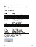
1-9-4. Diag Mode (Offline Defect Diagnosis Function)
1. Execution environment
This diagnostic function can be executed in the following environment.
2. Equipment, software
PC for terminal
Windows PC (Windows 2000 or later)
Terminal software
TeraTermPro ver. utf8-4.53 (Be sure to use this version)
Diagnostic TeraTerm macro for ver. 1.00
Connection cable
When the PC side is RS – 232C: An RS-232C-RS-232C cable is required.
(D-Sub 9-pin cross cable)
When the PC side is USB:
A USB – RS-232C conversion cable and
an RS-232C – RS-232C cross cable are
required.
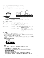
3. Settings
.
Prepare the PC on which Windows 2000 or later operates normally.
.
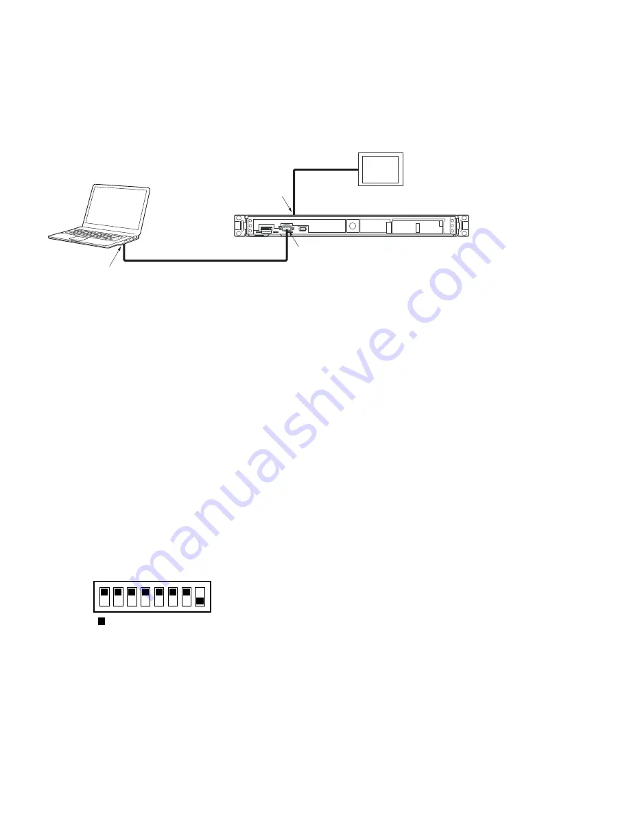
Remove the front panel of the BCU-100 unit and connect the RS-232C connector on the front and the
RS-232C connector of the PC with a serial cross cable.
If the PC has no RS-232C connector, use the USB – RS-232C conversion cable to connect to the USB
connector.
.
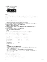
Set the front DIP switch as follows.
1 to 7 : OFF
8 :
ON
n
After the diagnosis, be sure to return the DIP switch to the original setting (8: OFF).
.
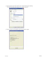
Install the terminal software TeraTermPro into the PC.
.
Install TeraTerm macro into the folder in which the TeraTermPro executable file is installed.
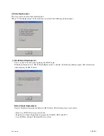
Macro installation procedure
(1) Extract the macro in a desired folder.
(2) Copy all the macro files in the folder to the folder in which TeraTermPro is installed.
(3) Create a shortcut for “ttpmacro.exe” located in the folder in which TeraTermPro is installed.
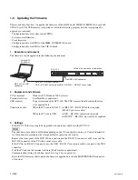
Front RS-232C connector
RS-232C – RS-232C cable or
USB – RS-232C conversion cable + RS-232C – RS-232C cross cable
RS-232C or USB
connector
Monitor
DVI cable
DVI-I terminal
on the rear panel
BCU-100
Terminal PC
(Windows)
<When the front panel is removed>
1
2
3
4
5
6
7
8
OFF
ON
( indicates the knob position.)


