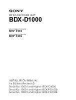
background image

MPEG DECODER UNIT

BDX-D1000

DESCRAMBLER BOARD

BDKP-D1003

DESCRAMBLER BOARD

BDKP-D1004

INSTALLATION MANUAL
1st Edition (Revised 5)
Serial No. 10001 and Higher: BDX-D1000
Serial No. 10001 and Higher: BDKP-D1003
Serial No. 10001 and Higher: BDKP-D1004

Summary of Contents for BDKP-D1003

Page 1: ...DX D1000 DESCRAMBLER BOARD BDKP D1003 DESCRAMBLER BOARD BDKP D1004 INSTALLATION MANUAL 1st Edition Revised 5 Serial No 10001 and Higher BDX D1000 Serial No 10001 and Higher BDKP D1003 Serial No 10001 and Higher BDKP D1004 ...

Page 2: ...de blessure n effectuer que les réparations indiquées dans le mode d emploi à moins d être qualifié pour en effectuer d autres Pour toute réparation faire appel à une personne compétente uniquement Attention when the product is installed in Rack For BDX D1000 1 Prevention against overloading of branch circuit When this product is installed in a rack and is supplied power from an outlet on the rack...

Page 3: ...8 E 1 8 1 DAC 31 Board 1 8 E 1 8 2 DEC 99 Board SUFFIX 14 and Higher 1 9 E 1 8 3 DEC 99 Board SUFFIX 11 through 13 1 10 E 1 9 Settings of Parameters 1 11 E 2 Installation of Optional Boards 2 1 General Information for Installation 2 1 E 2 2 BDKP D1003 D1004 Installation 2 2 E 3 Service Overview 3 1 Cleaning of Air Filter 3 1 E 3 2 Description of Internal Indicators 3 2 E 3 2 1 DAC 31 Board 3 2 E 3...

Page 4: ......

Page 5: ...pplied with the BDX D1000 This manual describes information that premise the service based on board replacement and parts replacement adjustments board layouts schematic dia grams parts list etc If this manual is required contact your local Sony Sales Office Service Center Contents The following is a summary of all the sections for understanding the contents of this manual Section 1 Installation E...

Page 6: ......

Page 7: ...lator is used for the power supply of the BDX D1000 The voltage within the range of 100 V to 240 V can be used without changing the supply voltage n As the inrush current at turn on is maximum 20 A at 100 V maximum 40 A at 240 V the capacity of the AC power must be adequate with the inrush current of maxi mum 20 A at 100 V maximum 40 A at 240 V If the capacity of the AC power is not the adequately...

Page 8: ...Connect the enough long cables on the rear panel considering that the BDX D1000 is pulled out An installation manual is supplied with the RMM 30 rack mount rail However follow the instructions in this manual Because the rack mounting procedures of the BDX D1000 are different from the procedures explained in RMM 30 installation manual To prevent falling the rack fix the rack on the horizontal firm ...

Page 9: ... the BDX D1000 may be dropped by insufficient strength of the rack mount rail This may cause a injury Procedures 1 Turn the power off 2 Remove the four feet from the bottom of the BDX D1000 1 4 Rack Mounting 3 While pressing the stopper of the rail pull out the inner rail 4 Attach the inner rails to the BDX D1000 using the six screws B4x8 supplied with the BDX D1000 5 Loosen the screws fastening t...

Page 10: ...tighten the screws B5x8 secured tempo rarily in the step 6 n When securing the front brackets to the rack by screws pull out the BDX D1000 about 20 cm 8 inches and fasten the screws of the front brackets to the rack 9 After installing the BDX D1000 in the rack secure the unit to the rack by the prepared four screws RK5x16 and four washers n When the BDX D1000 is mounted in a rack the maximum trave...

Page 11: ...61 749 00 Shell RS 232C 1 6 D sub 9 pin female Commercially available 10BASE T RJ45 modular jack 3 SDI VIDEO OUTPUT 1 BNC 75 Z male 1 569 370 12 2 5C 2V cable 2 DIGITAL AUDIO OUTPUT CH1 2 BNC 75 Z male 1 569 370 12 CH3 4 5C 2V cable 2 CH5 6 CH7 8 DATA OUT 10BASE T RJ45 modular jack 3 ANALOG VIDEO OUTPUT COMPOSITE BNC 75 Z male 1 569 370 12 COMPONENT ANALOG AUDIO OUTPUT CH1 XLR 3 pin female 1 508 0...

Page 12: ...ock B O 15 System GND 16 Data 7B MSB O 17 Data 6B O 18 Data 5B O 19 Data 4B O 20 Data 3B O 21 Data 2B O 22 Data 1B O 23 Data 0B O 24 DVALID B Data valid B O 25 PSYNC B Packet sync B O 2 2 2 2 2 RS 232C 1 1 D sub 9 pin Pin No Signal I O 1 2 RXD I 3 TXD O 4 5 GND 6 7 RTS O 8 CTS I 9 1 For any unit with a serial number 10001 to 10420 the connector is indicated as AUX and no signal is output from ther...

Page 13: ...SE T 8 pin Modular jack Pin No Signal I O 1 TXD O 2 TXD _ O 3 RXD I 4 5 6 RXD _ I 7 8 1 7 Switch Setting of Connector Panel Set the 75 Z termination switch of REF VIDEO for your purpose When the loop through output is not used set the 75 Z termination switch to ON This switch is factory set to OFF 1 6 Input and Output Signal of Connector 1 7 Switch Setting of Connector Panel External view 5 1 9 6 ...

Page 14: ...position 10 ms Factory setting OPEN upper position n After this setting is changed turn the power off and on again S101 4 5 1 6 8 A 5 Factory use Factory setting All switch levels are set to OPEN upper position S101 5 2 A 5 PCR Lock Mode Select switch OPEN upper position ATM mode Used when connected to a system where PCR jitters may occur CLOSE lower position Fast lock mode Used when connected to ...

Page 15: ...0 1 A 5 Program Mode Select switch Selects the program mode ON Single program mode Used when a single program stream is received OFF Multi program mode Used when a multi program stream is received Factory setting OFF upper position S200 2 A 5 Factory use Factory setting OFF upper position S200 3 A 5 Display Mode Select switch Selects the display mode ON Freeze mode Freezes the picture that is show...

Page 16: ...a Ethernet or by using the menu and the buttons on the front panel ON By an external computer via Ethernet REMOTE control OFF By using the menu and buttons LOCAL control Factory setting OFF upper position n When remote control mode is selected it can not be controlled from the front panel At this time is displayed on the PROGRAM indicator and is displayed on the AUDIO indicator S200 6 A 5 LNB Powe...

Page 17: ...er normal conditions S302 E 6 Factory use Factory setting All switch levers are set to ON S600 G 3 Factory use Factory setting All switch levers are set to ON 1 9 Settings of Parameters Set the parameters of the following menus as required TUNER SETTING menu Only when using the QPSK input INPUT STATUS menu Only when changing the input stream IP ADDRESS in SYSTEM INFO menu Only when using Ethernet ...

Page 18: ...t the requirements of video output for your purpose VIDEO CONTROL VITC AUTO VITC L1 L2 16 18 PACKET VBI OFF VIDEO INDEX ON LUMIN GAIN 0x800 CHROM GAIN 0x800 COMPONENT BETACAM HUE 0 deg SETUP 0 0IRE SYNC PHASE 0x800 SC PHASE 0 deg 1 AUDIO CONTROL menu Set the requirements of audio output for your purpose AUDIO CONTROL ADVANCE 0us CH1 2 GAIN 0dB CH3 4 GAIN 0dB CH5 6 GAIN 2 CH7 8 GAIN 2 RATE CONV AUT...

Page 19: ...ommon system BDKP D1004 Descrambler Board When the BDKP D1004 SCR 8 board is installed on the DEC 99 board it can be descrambled by DES system n Either BDKP D1003 or BDKP D1004 can be installed on the DEC 99 board The assignments of slots are as follows Slot No Front side Rear side 1 DEC 99 SCR 7 BDKP D1003 TSI 2 SCR 8 BDKP D1004 2 DIO 48 3 DAC 31 BF 72 Front side Slot No 1 2 3 DEC 99 DAC 31 Rear ...

Page 20: ...no necessity to confirm adjust after SCR 7 8 board installing 2 2 BDKP D1003 D1004 Installation Either BDKP D1003 SCR 7 board or BDKP D1004 SCR 8 board can be installed on the DEC 99 board Installation procedures 1 Turn the power off 2 Unplug the appliance from the outlet 3 Loosen the locking screw on the front panel using a flatblade screwdriver 4 Pull the locking screw toward you and open the fr...

Page 21: ...erature inside the unit getting rise This may cause a fire Procedures 1 Turn the power off 2 Loosen the locking screw on the front panel using a flatblade screwdriver 3 Pull the locking screw toward you and open the front panel 4 Peel the filter away from the tapes 5 Clean the dust on the filter using a vacuum cleaner n If the filter is too much dusty it is recommended to wash it When washing the ...

Page 22: ... 625 50 Hz PAL Detection indicator Lights up when there is a stream of 625 50 Hz PAL D202 A 4 green 525 60 Hz NTSC Detection indicator Lights up when there is a stream of 525 60 Hz NTSC D203 A 4 green Packet Length 204 bytes Detection indicator Lights up when a stream has a packet length of 204 bytes D204 A 4 green Packet Length 188 bytes Detection indicator Lights up when a stream has a packet le...

Page 23: ...computer D702 F 2 red LAN Collision Detect indicator Lights up when a collision is detected at Ethernet port D800 A 4 green REF Input Detection indicator Lights up when an external synchronous video signal is detected D801 A 4 green Frame Synchronizer indicator Lights up when the frame synchronizer is running D802 A 4 green Picture Skip Detection indicator Lights up when the frame synchronizer s p...

Page 24: ...gement functions Model name Serial number ROM version 3 2 Description of Internal Indicators 3 3 ISR 3 2 3 DEC 99 Board SUFFIX 11 through 13 n The addresses on the board are shown by marks D300 E 3 green CPU indicator Lights up during CPU runs properly D700 H 2 green LAN Transmitted indicator Lights up when data is transmitted to Ethernet port D701 G 2 green LAN Link indicator Lights up when Ether...

Page 25: ...ce Service Center The preparation below is required when managing the BDX D1000 by ISR 1 Connect a personal computer to the RS 232C connec tor D sub 9 pin of the BDX D1000 using a RS 232C cross cable 2 Set the DIP switch S200 4 on the DEC 99 board to ON lower position 3 Install the ISR application program software to the personal computer BDX D1000 rear panel Personal computer RS 232C cross cable ...

Page 26: ... DTR NC 1 2 3 4 5 6 7 8 9 10 11 12 13 14 15 16 17 18 19 20 21 22 23 24 25 3 2 7 8 6 5 1 4 9 Information of ISR Connector Prepare a cable referred to the following connection In case of direct connection with a personal computer DB9 PC BDX DB9 Signal Signal FG TXD RXD RTS CTS DSR SG DCD DTR NC FG TXD RXD RTS CTS DSR SG DCD DTR NC 3 2 7 8 6 5 1 4 9 3 2 7 8 6 5 1 4 9 ...

Page 27: ...a host computer via LAN Terminal Server 6 pin port n The connection will change according to the maker of terminal server RJ12 Modular type Terminal Server BDX DB9 RTS TXD SG NC RXD CTS FG TXD RXD RTS CTS DSR SG DCD DTR NC 1 2 3 4 5 6 3 2 7 8 6 5 1 4 9 ...

Page 28: ... execute the specified self diagnostics Test numbers and descriptions are as follows Test No Description 2 DEC Board 3 TSI Board 4 DIO Board 5 DAC Board 6 DP Board It can be requested these self diagnostics menus by using HELP TST command When the self diagnostics is completed the BDX D1000 returns ATN OPC 3 3 3 Supported Commands The BDX D1000 supports the following commands For more detailed inf...

Page 29: ...eturns ATN OPC TST Test Query This command requests the results of the self diagnostics stored in the buffer The responses for each self diagnostics are as follows 2 DEC Board OK ERROR 3 TSI Board OK ERROR 4 DIO Board OK ERROR 5 DAC Board OK ERROR 6 DP Board OK ERROR FLAGS Flag Query This command requests the flag information The following five flags are defined Power cycled on Returns yes only on...

Page 30: ... in red it is judged that any one of the following three items are causes An overcurrent flowed to the LNB Low Noise Block The fan motor stopped Abnormality detected in the power unit Follow the steps below 1 Put S200 6 A 5 on the DEC 99 board to OFF n S200 6 LNB Power Select switch ON Power is provided from the IF terminal OFF Power is not provided from the IF terminal 2 Turn the power off and on...

Page 31: ... de Sony Corporation Sony Corporation interdit formellement la copie de quelque partie que ce soit de ce manuel ou son emploi pour tout autre but que des opérations ou entretiens de l équipement à moins d une permission écrite de Sony Corporation Das in dieser Anleitung enthaltene Material besteht aus Informationen die Eigentum der Sony Corporation sind Die Sony Corporation untersagt ausdrücklich ...

Page 32: ...Printed in Japan Sony Corporation 2001 12 11 B P Company 1998 BDX D1000 SY BDKP D1003 SY BDKP D1004 SY J E 3 200 104 06 ...

Reviews: