


1-8 (E)
BDX-D1000
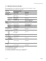
1-8. Settings of Internal Switches
1-8. Settings of Internal Switches
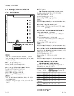
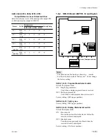
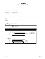
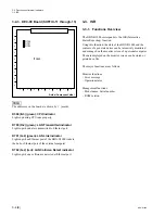
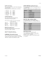
1-8-1. DAC-31 Board
n
.
The addresses on the board are shown by ( ) marks.
.
For the switches described “Factory use”, do not change
the factory setting.
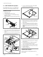
S101-1 (A-5) : Factory use
Factory setting : OPEN (upper position).
S101-2 (A-5) : D1/D2 Output Select switch
Selects the SDI output mode as follows :
OPEN (upper position) : D1 mode
CLOSE (lower position) : D2 mode
Factory setting : OPEN (upper position).
n
.
For any unit with a serial number 10001 to 10420, this
switch is not used.
.
After this setting is changed, turn the power off and on
again.
A side (Component side)
1
2
3
4
5
6
7
8
9
10
11
12
13
A
B
C
D
E
F
G
H
J
K
L
M
S101
S704
S706
S703
S705
S554
S556
S553
S555
S404
S406
S403
S405
Factory setting
1 2 3 4 5 6 7 8
OPEN
*
1: Serial No.10001 through 11000
*
2: Serial No.11001 and Higher
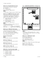
S101-3
*
*
*
*
*
2
(A-5) :
PCR Reload Threshold Time Select switch
Check the time between PCR to STC COUNTER.
OPEN (upper position)
: 2.7 ms
CLOSE (lower position) : 10 ms
Factory setting : OPEN (upper position)
n
After this setting is changed, turn the power off and on again.
S101-4, 5
*
*
*
*
*
1
, 6, 8 (A-5) : Factory use
Factory setting : All switch levels are set to OPEN (upper
position).
S101-5
*
*
*
*
*
2
(A-5) : PCR Lock Mode Select switch
OPEN (upper position) : ATM mode
Used when connected to a system where PCR jitters
may occur.
CLOSE (lower position) : Fast lock mode
Used when connected to a system where PCR jitters
will not occur.
Factory setting : OPEN (upper position)
n
After this setting is changed, turn the power off and on again.
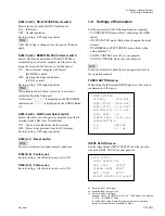
S101-7
*
*
*
*
*
2
(A-5) : Color Framing Mode Select switch
Select H-shift ON/OFF in Ref Lock mode. (Composite Only)
OPEN (upper position)
: AUTO
CLOSE (lower position) : OFF
Factory setting : CLOSE (lower position)
n
After this setting is changed, turn the power off and on again.
S403, S404, S553, S554, S703, S704:
Output Headroom Select switches
Select the headroom of the analog audio output CH1 to
CH4 and monitor output LCH/RCH.
Channel
Switch
Headroom
Factory Setting
20 dB 18 dB 16 dB
CH1
S554 (D-10)
20
18
16
20
CH2
S553 (F-10)
20
18
16
20
CH3
S404 (H-10)
20
18
16
20
CH4
S403 (J-10)
20
18
16
20
L
S703 (C-10)
20
18
16
20
(MONITOR)
R
S704 (A-10)
20
18
16
20
(MONITOR)


