


2-2 (E)
BDX-M1000
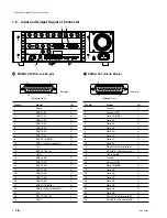
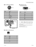
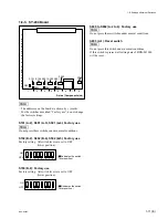
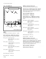
2-2. Description of Internal Indicators
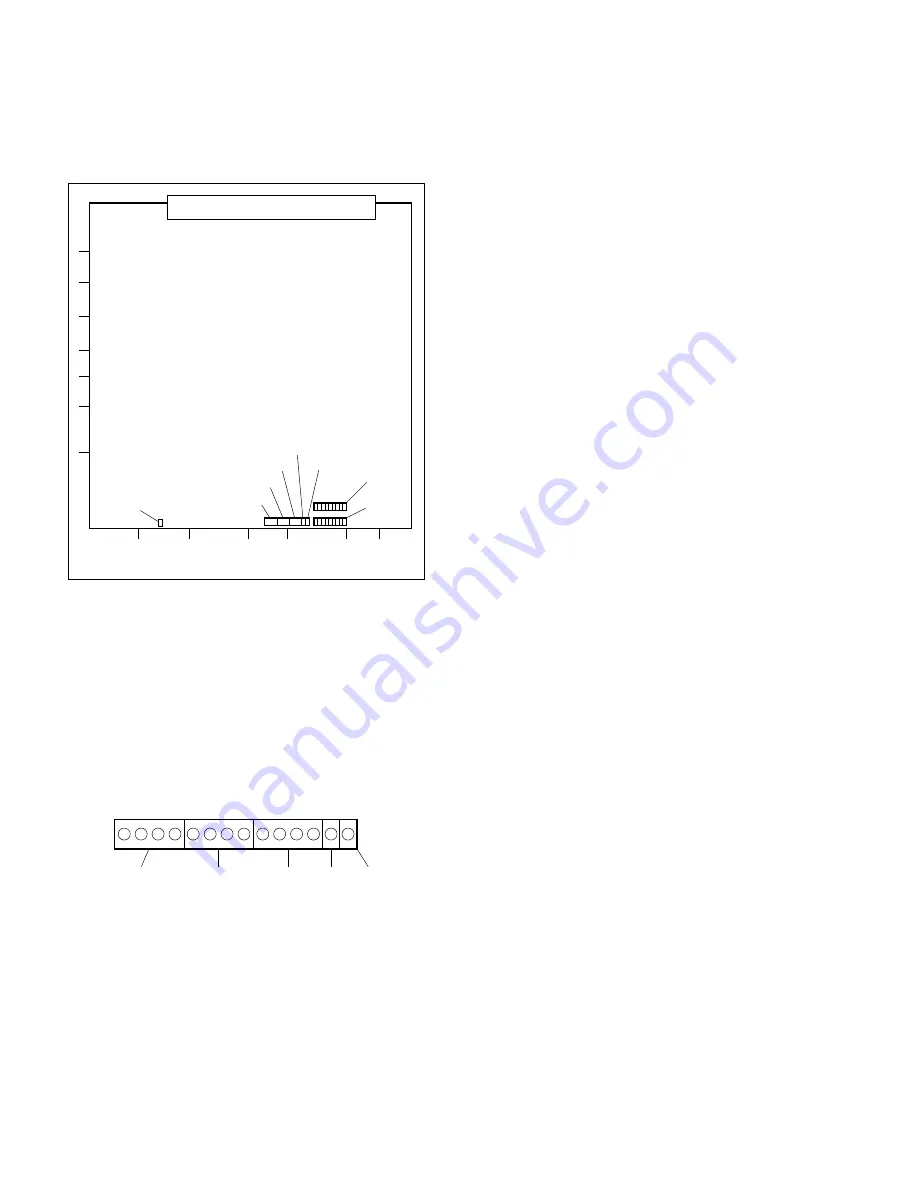
7
6
5
4
3
2
1
A
B
C
D
E
F
G
H
D201
D202
D203
D204
D205
D1611
D1612
D1620
-
D1601
D1610
-
A Side (Component side)
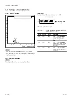
2-2. Description of Internal Indicators
2-2-1. IPM-81 Board
n
The addresses on the board are shown by ( ) marks.
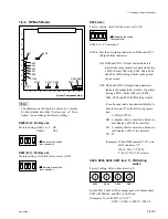
D201 to D203 (A-4, 5) (green),
D204, D205 (A-5) (red) : Status indicator
Indicates the result of the self-diagnostics at just after the
power on.
.
If an error is detected :
Both of D204 and D205 light up, and D201 to D203
indicate the description of error.
D201-1 : Lights up when DRAM error occurs.
D201-2 : Lights up when Dual-port RAM error occurs.
D201-3 : Unassigned
D201-CH1, D202, D203 :
Lights up when control error occurs at input
channel. (Refer to the figure for the correspon-
dance of the indicators and the channels.)
n
When any error is detected, the operation of CPU will
come to stop.
.
If an error is not detected (CPU starts up
properly) :
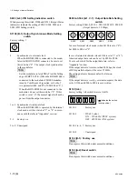
D201 to D204 indicate the following information.
D201-1 : CPU Operation indicator
Blinks at intervals of two seconds during CPU
operating.
D201-2 : Communication indicator
Lights up when this board communicates with
the CPU on the SY-244 board.
D201-3 : Unassigned
D201-CH1, D202, D203 : Channel Status indicator
Indicate the state of input channel on the basis
of S201-5 to -7 settings. (Refer to the Section
1-8-1)
D204 : Channel Error indicator
When S201-5 is set to OFF :
Blinks when some error occurs at the input
circuit.
When S201-5 is set to ON :
Lights up when the channel overflowed at
input buffer exists.
D205 : Unassigned
1
2
3
CH1 (CH10)
CH2 (CH11)
CH3 (CH12)
CH4 (CH13)
CH5 (CH14)
CH6 (CH15)
CH7 (CH16)
CH8 (CH17)
CH9 (CH18)
D204 D205
D203
D202
D201


