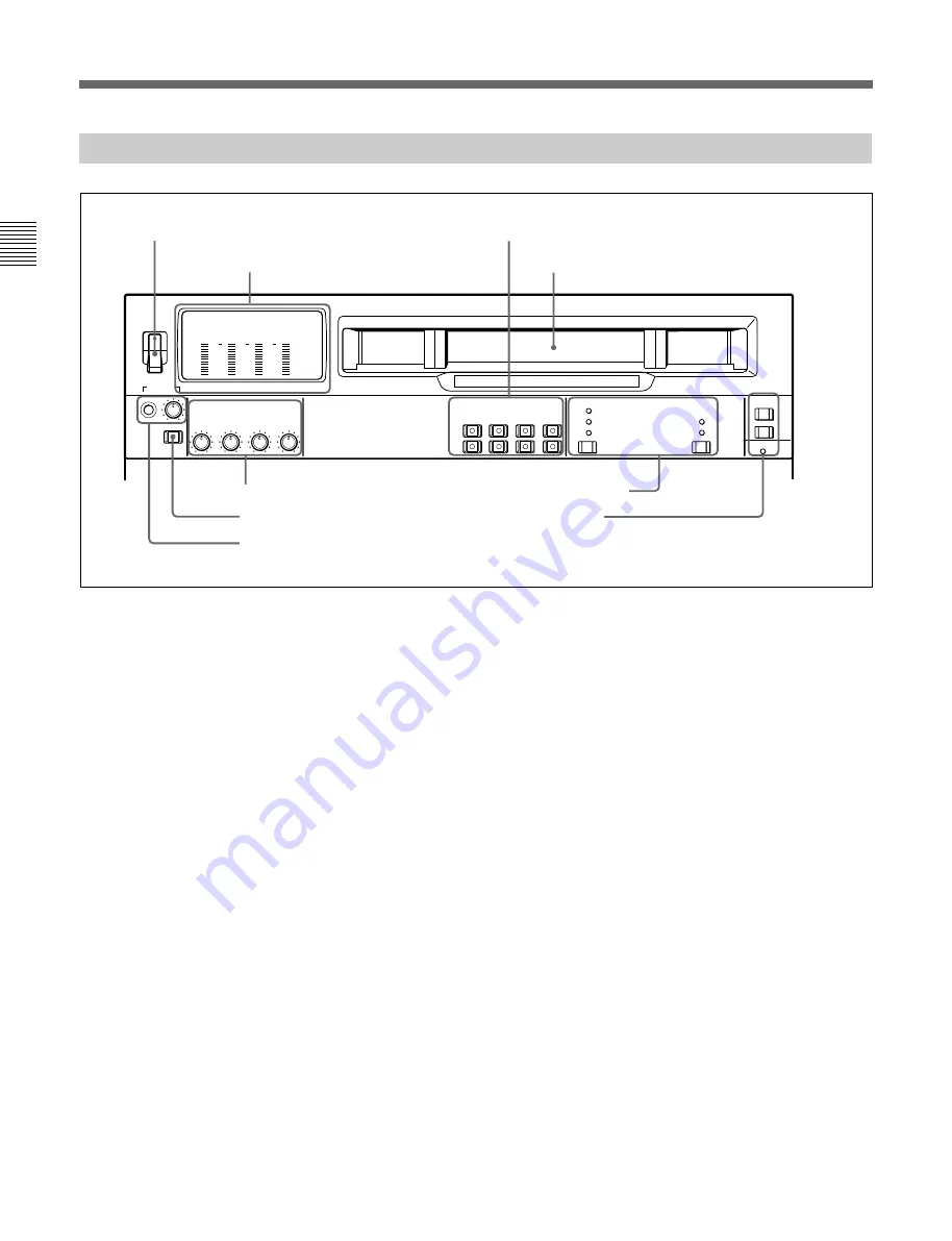
2-1 Control Panels
Chapter 2
Location and Function of Parts
2-2
Chapter 2
Location and Function of Parts
4
PB (playback) controls
These adjust individually the playback levels on
channels 1 to 4.
During playback, pull out the control knobs and adjust
the level while monitoring the audio level indication
on the level meters
2
.
When the control knobs are pushed in, the playback
levels return to the preset levels, and cannot be
adjusted.
5
DISPLAY FULL/FINE switch
This switches the audio level meter
2
display as
follows:
FULL: The display covers the range – 60 dB to 0 dB
or – 40 dB to +20 dB as selected using extended
menu item 806.
In this mode the segment of the display
corresponding to the current audio level and all
lower segments light.
FINE: The display is enlarged, with a step of 0.25
dB. A segment indicating the reference level
lights.
In this mode only the segment of the display
corresponding to the current audio level lights. If
the audio level exceeds the maximum display
level, the top segment flashes, and if the audio
level goes below the minimum display level, the
bottom segment flashes.
-20
PHONES
DISPLAY
FULL/FINE
CH-1
CH-2
CH-3
CH-4
CH-1
CH-2
CH-3
CH-4
POWER
PULL FOR VARIABLE
PB
ON
OFF
-80
-20
-30
-40
-10
0
dB
-80
-20
-30
-40
-10
0
dB
-80
-30
-40
-10
0
dB
-80
-20
-30
-40
-10
0
dB
L
R
CH-1
CH-2
CH-3
CH-4
LTC
TC
AUTO
VITC
DF
NDF
1(9P)
AUDIO MONITOR SELECT
ANALOG / DIGITAL
REMOTE
2(50P)
RS-232C
1
POWER
switch
2
Level meters
8
REMOTE buttons and
RS-232C indicator
Cassette compartment
2-1-1 Upper Control Panel
1
POWER switch
This powers the unit on and off. When the unit is
powered on, the level meters
2
and the fluorescent
display in the lower control panel light.
To power the unit off, press the side of the POWER
switch marked “OFF”.
2
Level meters
These show the audio playback levels of channels 1 to
4.
There are two modes for audio level indications:
FULL and FINE, selected by the DISPLAY FULL/
FINE switch
5
.
3
AUDIO MONITOR SELECT buttons
Press the buttons in the L and R rows to select the
audio signal channels output from the MONITOR
OUTPUT L and MONITOR OUTPUT R connectors.
You can press two or more buttons simultaneously in
each row, turning them on, to monitor an output
produced by mixing the selected channels.
3
AUDIO MONITOR SELECT buttons
4
PB controls
5
DISPLAY FULL/FINE switch
6
PHONES jack and control
7
Time code setting section
Summary of Contents for Betacam SX DNW-A65
Page 1: ...DIGITAL VIDEOCASSETTE PLAYER DNW A65 A65P OPERATION MANUAL English 1st Edition Revised 5 ...
Page 8: ......
Page 26: ......
Page 34: ......
Page 50: ......
Page 70: ......
Page 74: ......
Page 82: ...Printed in Japan 2001 07 13 1999 Sony Corporation B P Company DNW A65 A65P SYL 3 865 232 06 1 ...


