Chapter 6
Menu System
6-2
Chapter 6
Menu System
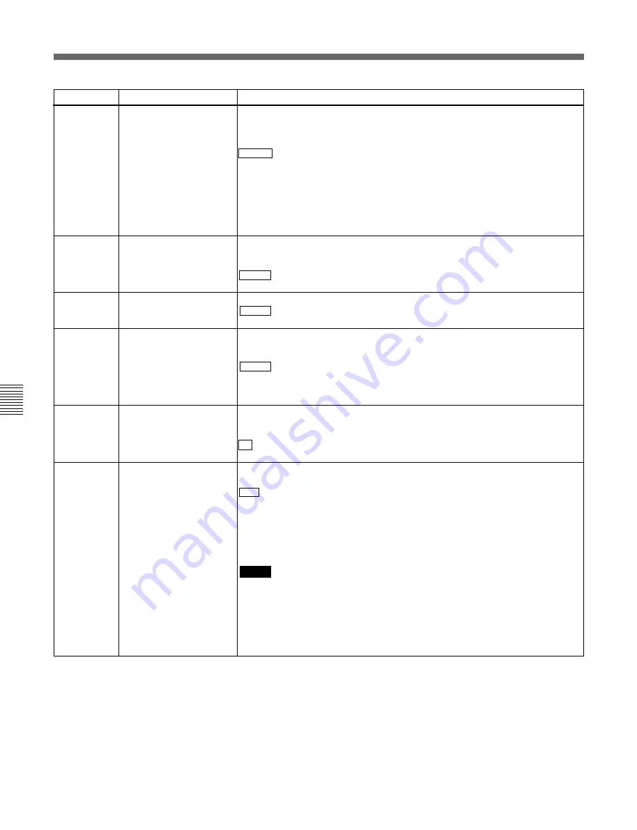
6-2 Basic Menu
Item number
Item name
Settings
006
LOCAL FUNCTION
ENABLE
Determines which buttons on the control panel are enabled when this unit is
controlled from external equipment.
DIS: All buttons and switches are disabled.
ST&EJ : Only the STOP button and EJECT button are enabled.
ENA: All buttons and switches are enabled.
007
TAPE TIMER DISPLAY
Determines whether to display the CTL count in 12-hour mode or 24-hour mode.
+ –12H : 12-hour mode
24H: 24-hour mode
009
a)
CHARACTER TYPE
Determines the type of characters such as time code output from the
COMPOSITE VIDEO OUTPUT 3 (SUPER) connector and the SDI OUTPUT 3
(SUPER) connector for superimposed display on the monitor.
WHITE : White letters on a black background.
BLACK: Black letters on a white background.
W/OUT: White outline letters.
B/OUT: Black outline letters.
011
a)
CHARACTER V-SIZE
Determines the vertical size of characters such as time code output from the
COMPOSITE VIDEO OUTPUT 3 (SUPER) connector and the SDI OUTPUT 3
(SUPER) connector for superimposed display on the monitor.
X1 : Standard size
X2: 2 times standard size
a) When setting items 009 and 011, watch the monitor
screen, and adjust to the required state.
005
DISPLAY INFORMATION
SELECT
Determines the kind of character information to be output from the COMPOSITE
VIDEO OUTPUT 3 (SUPER) connector and the SDI OUTPUT 3 (SUPER)
connector when the CHARACTER switch on the subsidiary control panel is set to
ON.
T&STA : Time data display information and the unit’s status.
T&UB: Time data display information and the user’s bits.
T&CTL: Time data display information and CTL.
T&T: Time data display information and time code (LTC or VITC).
TIME: Time code (LTC or VITC) only.
If there is a overlap between the setting of this item and the setting of the control
panel, it is automatically avoided. For example, if CTL is selected on the control
panel and this menu item setting is T&CTL, then CTL and LTC are output.
013
525/625 SYSTEM
SELECT
Before using this menu
item, consult the person
responsible for the
installation.
Specify whether to enable switching between the 525 (NTSC) and 625 (PAL)
systems.
OFF : Do not enable system switching.
ON: Enable system switching.
Setting this item to ON and switching the system enables the unit to operate in
the system switched to.
For the switching between 525/625 line systems, see page 6-6.
Notes
• For the basic and extended menus, separate settings are saved for 525 (NTSC)
and 625 (PAL) modes. When you switch systems, all menu items change to the
settings established in the new system. (These are different from the settings for
the mode before switching.)
• When the DNW-A65 is used in the 625 mode or when the DNW-A65P is used in
the 525 mode, Betacam and Betacam SP tape can only be played back in the
simple playback mode.
Summary of Contents for Betacam SX DNW-A65
Page 1: ...DIGITAL VIDEOCASSETTE PLAYER DNW A65 A65P OPERATION MANUAL English 1st Edition Revised 5 ...
Page 8: ......
Page 26: ......
Page 34: ......
Page 50: ......
Page 70: ......
Page 74: ......
Page 82: ...Printed in Japan 2001 07 13 1999 Sony Corporation B P Company DNW A65 A65P SYL 3 865 232 06 1 ...


