DVS-7000AE IM
5-3
5-1. Switch Settings on Boards and LEDs Description
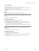
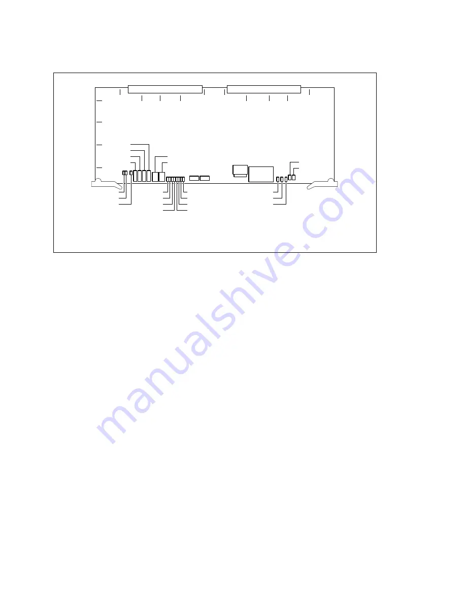
2. CPU-264 Board
CNT3
(B5) :
+
5 V TEST terminal
This terminal is used to measure the
+
5 V voltage.
When re-adjusting the voltage after installing the option board to the unit, this terminal is used.
CNT4
(B5) :
+
3 V TEST terminal
This terminal is used to measure the
+
3 V voltage.
When re-adjusting the voltage after installing the option board to the unit, this terminal is used.
CNT6
(C5) :
_
5 V TEST terminal
This terminal is used to measure the
_
5 V voltage.
When re-adjusting the voltage after installing the option board to the unit, this terminal is used.
CNT7
(C5) : GND TEST terminal
This terminal is the reference against the
+
5 V,
+
3 V and
_
5 V TEST terminals.
CN8
(G5) : LAN connector
This connector is used for the adjustment in the factory.
CN9
(H5) : TERMINAL connector
This connector complies with the RS-232C standard, and is connected to the control terminal for the
adjustment in the factory and the maintenance.
D15
D16
D18
D1
D2
D3
D4
D8
D7
D6
D5
D14
D12
D13
CNT7
CNT6
CNT4
CNT3
D100
D101
S1
1
A
F
L
B
C
D
E
G
H
J
K
2
3
4
5
CN8
CN9
S2
S3
S4
CPU-264 board
(Component side/A side)


