5-4
DVS-7000AE IM
5-1. Switch Settings on Boards and LEDs Description
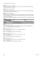
D1 through D8
(Green colors) (D5/E5) : STATUS displays
These LEDs are used for the adjustment in the factory.
D15
(Yellow color) (B5) :
+
5 V
This LED is displayed the status of the
+
5 V source for all system.
Light ;
Normal status.
Light off ; The power does not provide to the CPU-264 board or the fuse on the CPU-264 or CA-35A
board blows.
D16
(Yellow color) (B5) :
+
3 V
This LED is displayed the status of the
+
3 V source for all system.
Light ;
Normal status.
Light off ; The power does not provide to the CPU-264 board or the fuse on the CPU-264 or CA-35A
board blows.
D18
(Green color) (B5) :
_
5 V
This LED is displayed the status of the
_
5 V source for all system.
Light ;
Normal status.
Light off ; The power does not provide to the CPU-264 board or the fuse on the CPU-264 or CA-35A
board blows.
D14
(Yellow color) (J5) : VD
When the VD signal provides at regular intervals from the CA-35A board and is normal operated, this
LED lights.
D12
(Green color) (J5) : RUN
When the CPU is normal operated, this LED lights.
D13
(Red color) (J5) : FAIL
When the CPU is stopped by some source, this LED lights.
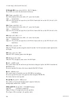
S3
(K5) : ABORT switch
This switch is used when the unit starts up in the factory settings (except for the D1/D2 format and the
RESUME mode).
The unit is operated the same as the clear command of the SET UP menu.
S4
(K5) : RESET switch
This switch is used to forcefully restart the SYSTEM by the hardware.
The unit is operated the same as the operation when turning the POWER ON.
The resume function is not operated.
S1 and S2
(E5) and
(F5) : DBG switch
This switch is a 8-pin dip switch and is used to adjust in the factory.
Settings under normal status : All OFF
D100 and D101
(C5) and
(D5) : 7 SEGMENT displays
Light off;
The power is turned ON.
Display the figure; The application starts the operation.
These figures differ according to the operation mode.


